Infiniti FX35, FX50 (S51). Manual — part 1410
PB-8
< REMOVAL AND INSTALLATION >
PARKING BRAKE SHOE
Note the following, install in the reverse order of removal.
• Apply PBC (Poly Butyl Cuprysil) grease or silicone-based grease to the back plate and brake shoe.
CAUTION:
The parking brake shoes for the front wheels are made of different materials from those for the rear
wheels. Never misidentify them when removing and replacing.
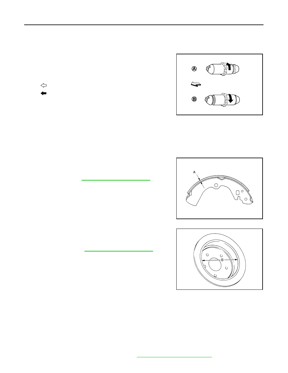
• Assemble adjusters so that threaded part is expanded when rotat-
ing it in the direction shown by arrow.
• Shorten adjuster by rotating it.
• When disassembling apply PBC (Poly Butyl Cuprysil) grease or sil-
icone-based grease to threads.
• Check brake shoe sliding surface and drum inner surface for
grease. Wipe it off if it adhere on the surfaces.
Inspection and Adjustment
INFOID:0000000005234472
INSPECTION AFTER REMOVAL
Lining Thickness Inspection
• Check thickness (A) of lining.
Drum Inner Diameter Inspection
• Check inner diameter (B) of drum.
Other Inspections
Check the following items, and replace the parts if necessary.
• Lining for excessive wear, damage, and peeling.
• Brake shoe sliding surface for excessive wear and damage.
• Anti-rattle pin and retainer for excessive wear, damage and rust.
• Adjuster spring, return spring and anti-rattle spring for settling, excessive wear, damage, and rust.
• Adjuster for smoothness.
• Toggle lever for excessive wear, damage and rust.
• Visually check inside of the drum for excessive wear, cracks, and damage with a pair of vernier calipers.
ADJUSTMENT AFTER INSTALLATION
1.
Adjust the parking brake pedal stroke. Refer to
PB-3, "Inspection and Adjustment"
A : For right side brake
B : For left side brake
: Vehicle front
: Adjuster expands
JPFIB0009ZZ
Limit
A
: Refer to
.
SBR021A
Limit
B
: Refer to
.
JPFIB0008ZZ

PARKING BRAKE SHOE
PB-9
< REMOVAL AND INSTALLATION >
C
D
E
G
H
I
J
K
L
M
A
B
PB
N
O
P
2.
Check a drag of the parking brake.
CAUTION:
If any drag is found, inspect the rear disc brake. Refer to
BR-60, "BRAKE CALIPER ASSEMBLY (1
(1 piston type),
BR-64, "BRAKE CALIPER ASSEMBLY (2 PISTON
(2 piston type).
3.
Adjust the parking brake shoe. Refer to

PB-10
< SERVICE DATA AND SPECIFICATIONS (SDS)
SERVICE DATA AND SPECIFICATIONS (SDS)
SERVICE DATA AND SPECIFICATIONS (SDS)
SERVICE DATA AND SPECIFICATIONS (SDS)
Parking Drum Brake
INFOID:0000000005234473
Unit: mm (in)
Parking Brake Control
INFOID:0000000005234474
Item
Limit
Brake lining
1.5 (0.059)
Drum (disc of inner diameter)
191 (7.52)
Item
Standard
Number of notches [under force of 196 N (20 kg, 44 lb)]
2 – 3 notches
Number of notches when brake warning lamp turns ON
1 notch
PCS
PCS-1
ELECTRICAL & POWER CONTROL
C
D
E
F
G
H
I
J
K
L
B
SECTION
PCS
A
O
P
N
CONTENTS
POWER CONTROL SYSTEM
IPDM E/R
SYSTEM DESCRIPTION . . . . . . . ..
RELAY CONTROL SYSTEM . . . . . . . ..
System Diagram . . . . . . . . . . . . . ....
System Description . . . . . . . . . . . . ...
Component Parts Location . . . . . . . . . ....
POWER CONTROL SYSTEM . . . . . . . .
System Diagram . . . . . . . . . . . . . ....
System Description . . . . . . . . . . . . ...
Component Parts Location . . . . . . . . . ....
SIGNAL BUFFER SYSTEM . . . . . . . .
System Diagram . . . . . . . . . . . . . ....
System Description . . . . . . . . . . . . ...
Component Parts Location . . . . . . . . . ....
POWER CONSUMPTION CONTROL SYS-
TEM . . . . . . . . . . . . . . . . . .
System Diagram . . . . . . . . . . . . . ....
System Description . . . . . . . . . . . . ...
Component Parts Location . . . . . . . . . ..
DIAGNOSIS SYSTEM (IPDM E/R) . . . . . .
Diagnosis Description . . . . . . . . . . . .
CONSULT-III Function (IPDM E/R) . . . . . . .
DTC/CIRCUIT DIAGNOSIS . . . . . . .
U1000 CAN COMM CIRCUIT . . . . . . . .
Description . . . . . . . . . . . . . . . ..
DTC Logic . . . . . . . . . . . . . . . ...
Diagnosis Procedure . . . . . . . . . . . ...
B2098 IGNITION RELAY ON STUCK . . . ...
Description . . . . . . . . . . . . . . . ..
DTC Logic . . . . . . . . . . . . . . . ...
Diagnosis Procedure . . . . . . . . . . . ...
B2099 IGNITION RELAY OFF STUCK . . . ..
Description . . . . . . . . . . . . . . . ...
DTC Logic . . . . . . . . . . . . . . . .
Diagnosis Procedure . . . . . . . . . . . ...
POWER SUPPLY AND GROUND CIRCUIT .
Diagnosis Procedure . . . . . . . . . . . ...
ECU DIAGNOSIS INFORMATION . . . ..
IPDM E/R (INTELLIGENT POWER DISTRI-
BUTION MODULE ENGINE ROOM) . . . .
Reference Value . . . . . . . . . . . . . ..
Wiring Diagram - IPDM E/R - . . . . . . . . ..
Fail-safe . . . . . . . . . . . . . . . . ...
DTC Index . . . . . . . . . . . . . . . ...
PRECAUTION . . . . . . . . . . . ..
PRECAUTIONS . . . . . . . . . . . . .
Precaution for Procedure without Cowl Top Cover .
REMOVAL AND INSTALLATION . . . ...
IPDM E/R (INTELLIGENT POWER DISTRI-
BUTION MODULE ENGINE ROOM) . . . .
Exploded View . . . . . . . . . . . . . . .
Removal and Installation . . . . . . . . . . .
POWER DISTRIBUTION SYSTEM
BASIC INSPECTION . . . . . . . . ...
DIAGNOSIS AND REPAIR WORK FLOW . ...
Work Flow . . . . . . . . . . . . . . . .
SYSTEM DESCRIPTION . . . . . . . .
POWER DISTRIBUTION SYSTEM . . . . ...
System Description . . . . . . . . . . . . ..
Нет комментариевНе стесняйтесь поделиться с нами вашим ценным мнением.
Текст