Infiniti EX35. Manual — part 713

TIMING CHAIN
EM-51
< ON-VEHICLE REPAIR >
C
D
E
F
G
H
I
J
K
L
M
A
EM
N
P
O
Removal and Installation
INFOID:0000000003139117
REMOVAL
1.
Release the fuel pressure. Refer to
.
2.
Disconnect the battery cable from the negative terminal.
3.
Remove engine cover with power tool. Refer to
.
4.
Remove radiator reservoir tank. Refer to
5.
Remove air duct and air cleaner case assembly (RH and LH). Refer to
6.
Remove engine undercover with power tool.
7.
Drain engine coolant from radiator. Refer to
.
CAUTION:
• Perform this step when the engine is cold.
• Never spill engine coolant on drive belt.
8.
Remove radiator hose (upper and lower). Refer to
.
9.
Drain engine oil. Refer to
.
CAUTION:
• Perform this step when the engine is cold.
• Never spill engine oil on drive belt.
10. Remove drive belt. Refer to
.
11. Remove radiator cooling fan assembly. Refer to
.
12. Separate engine harnesses removing their brackets from front timing chain case.
13. Remove intake manifold collector. Refer to
14. Remove intake manifold. Refer to
15. Remove fuel sub tube mounting bolt. Refer to
16. Remove oil level gauge and oil level gauge guide.
17. Remove A/C compressor from bracket with piping connected, and temporarily secure it aside. Refer to
18. Remove power steering oil pump from bracket with piping connected, and temporarily secure it aside.
.
19. Remove power steering oil pump bracket. Refer to
20. Remove idler pulley, auto tensioner and bracket.
21. Remove alternator and alternator bracket. Refer to
(AWD models).
22. Remove water outlet (front) and water piping. Refer to
.
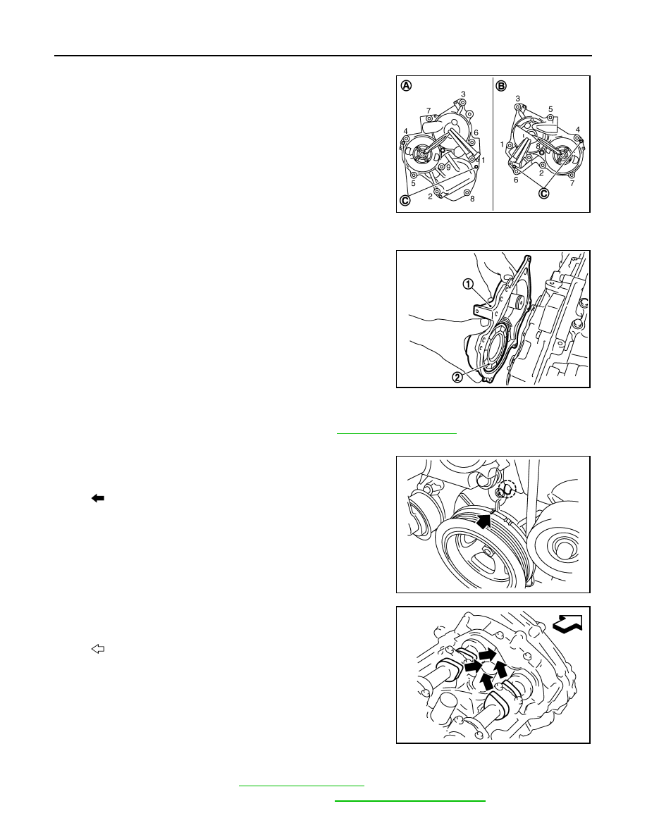
23. Remove valve timing control covers (bank 1 and bank 2) and gasket as follows:
10. Slack guide
11. Crankshaft sprocket
12.
Camshaft sprocket (INT)
13.
Valve timing control cover gasket
(bank 1)
14. Seal ring
15.
Valve timing control cover (bank 1)
16. O-ring
17.
Exhaust valve timing control sole-
noid valve (bank 1)
18.
Oil level gauge
19. Oil level gauge guide
20. O-ring
21.
Intake valve timing control solenoid
valve (bank 2)
22. Valve timing control cover (bank 2)
23.
Exhaust valve timing control sole-
noid valve (bank 2)
24.
Valve timing control cover gasket (bank
2)
25. Front oil seal
26. Crankshaft pulley
27.
Crankshaft pulley bolt
28.
Intake valve timing control solenoid
valve (bank 1)
29. Power steering oil pump bracket
30.
Idler pulley bracket
31. Alternator bracket
32. Water outlet (front)
33.
Front timing chain case
34. Rear timing chain case
35. O-ring
36.
O-ring
37. O-ring
A.
Refer to
B.
C.
Oil filter
Refer to
for symbols in the figure.
EM-52
< ON-VEHICLE REPAIR >
TIMING CHAIN
a.
Disconnect valve timing control harness connector.
b.
Loosen mounting bolts in reverse order as shown in the figure.
CAUTION:
Shaft is internally jointed with camshaft sprocket (INT) cen-
ter hole. When removing, keep it horizontal until it is com-
pletely disconnected.
c.
Shaft is engaged with intake side camshaft sprocket center hole on inside. pull straight out so as not to tilt
until the joint is disengaged.
• The mating surface of magnet retarder (2) may be fitted with
the exhaust side camshaft sprocket via the engine oil. Open
valve timing control cover (1) carefully
• If the mating surface of magnet retarder is fitted with the cam-
shaft sprocket, open the cover within the range that the load is
not applied to the harness. And then, remove it so as to pre-
vent magnet retarder from dropping.
CAUTION:
• Be careful not to damage magnet retarder.
• When carrying valve timing control cover, face the mag-
net retarder side up to prevent the cover from falling from
magnet retarder.
• Never remove magnet retarder from valve timing control cover. (Disassembly prohibited parts)
24. Remove rocker covers (bank 1 and bank 2). Refer to
25. Obtain No. 1 cylinder at TDC of its compression stroke as follows:
a.
Rotate crankshaft pulley clockwise to align timing mark (grooved
line without color) with timing indicator.
b.
Check that intake and exhaust cam noses on No. 1 cylinder
(engine front side of bank 1) are located as shown in the figure.
• If not, turn crankshaft one revolution (360 degrees) and align
as shown in the figure.
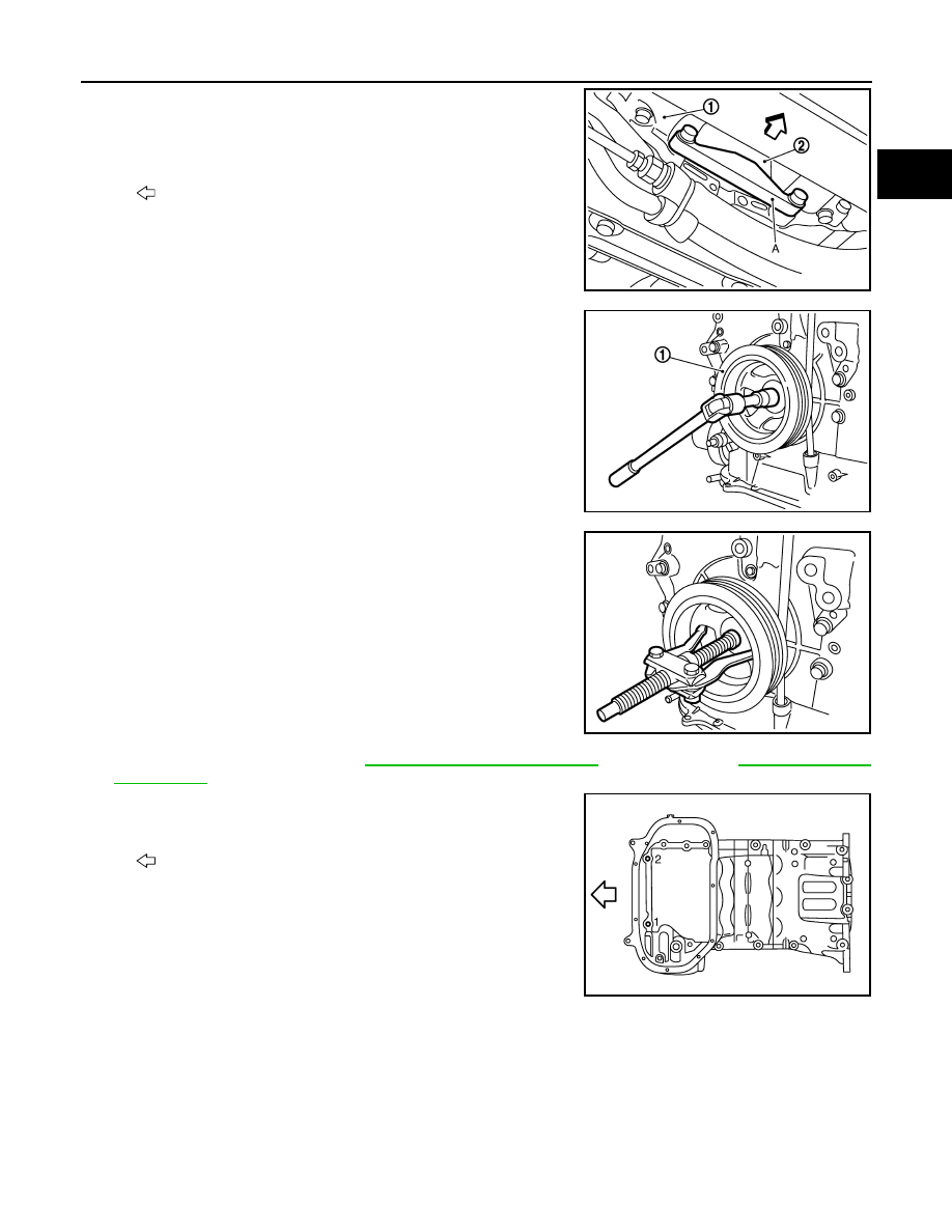
26. Remove crankshaft pulley as follows:
a.
Remove front cross bar. Refer to
. (AWD models)
b.
Remove power steering pipe mounting bolt. Refer to
A
: Bank 1
B
: Bank 2
C
: Dowel pin hole
JPBIA0041ZZ
JPBIA0042ZZ
: Timing mark (grooved line without color)
JPBIA0043ZZ
: Engine front
JPBIA0044ZZ
TIMING CHAIN
EM-53
< ON-VEHICLE REPAIR >
C
D
E
F
G
H
I
J
K
L
M
A
EM
N
P
O
c.
Remove rear cover plate and set the ring gear stopper [SST:
KV10118600 (J-48641)] (A) as shown in the figure.
d.
Loosen crankshaft pulley bolt and rotate bolt seating surface at
10 mm (0.39 in) from its original position.
CAUTION:
Never remove crankshaft pulley bolt as it will be used as a
supporting point for suitable puller.
e.
Place suitable puller tab on holes of crankshaft pulley, and pull
crankshaft pulley through.
CAUTION:
Never put suitable puller tab on crankshaft pulley periphery,
as this will damage internal damper.
27. Remove oil pan (lower). Refer to
(AWD models).
28. Loosen two mounting bolts in front of oil pan (upper) with power
tool in reverse order as shown in the figure.
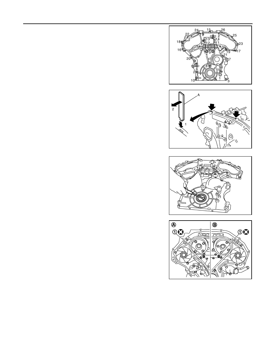
29. Remove front timing chain case as follows:
1
: Oil pan (upper)
2
: Drive plate
: Vehicle front
JPBIA0408ZZ
1
: Crankshaft pulley
JPBIA1364ZZ
JPBIA1368ZZ
: Engine front
JPBIA0047ZZ
EM-54
< ON-VEHICLE REPAIR >
TIMING CHAIN
a.
Loosen mounting bolts in reverse order as shown in the figure.
b.
Insert a suitable tool (A) into the notch at the top of front timing
chain case as shown.
c.
Pry off case by moving the suitable tool as shown.
• Use the seal cutter [SST: KV10111100 (J37228)] to cut liquid
gasket for removal.
CAUTION:
• Never use a screwdriver or something similar.
• After removal, handle front timing chain case carefully so
it does not tilt, cant, or warp under a load.
30. Remove front oil seal from front timing chain case using a suit-
able tool.
• Use a screwdriver for removal.
CAUTION:
Be careful not to damage front timing chain case.
31. Remove O-rings (1) from rear timing chain case.
32. Remove timing chain tensioner (primary) as follows:
JPBIA0046ZZ
JPBIA0048ZZ
JPBIA0049ZZ
A
: Bank 1
B
: Bank 2
JPBIA0406ZZ
Нет комментариевНе стесняйтесь поделиться с нами вашим ценным мнением.
Текст