Infiniti EX35. Manual — part 503
DLK-226
< ON-VEHICLE REPAIR >
[INTELLIGENT KEY SYSTEM]
FRONT DOOR
INSTALLATION
Install in the reverse order of removal.
CAUTION:
Check front door open/close operation after installation.

REAR DOOR
DLK-227
< ON-VEHICLE REPAIR >
[INTELLIGENT KEY SYSTEM]
C
D
E
F
G
H
I
J
L
M
A
B
DLK
N
O
P
REAR DOOR
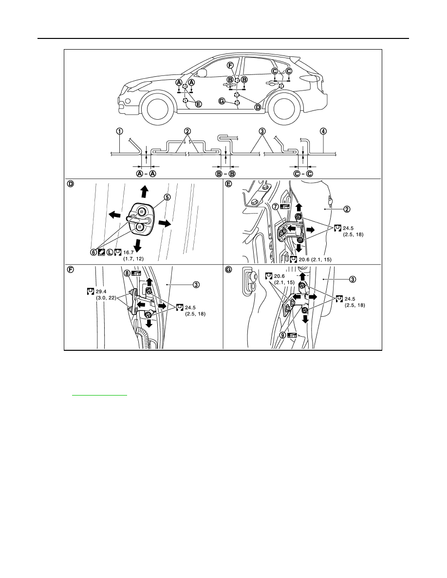
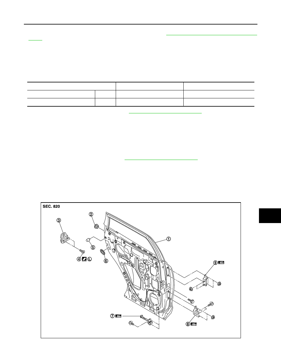
DOOR ASSEMBLY
DOOR ASSEMBLY : Exploded View
INFOID:0000000003556344
REMOVAL
ADJUSTMENT
1.
Rear door panel
2.
Grommet
3.
Door striker
4.
TORX bolt
5.
Seal rubber
6.
Bumper rubber
7.
Door check link
8.
Door hinge (lower)
9.
Door hinge (upper)
Refer to
JMKIA2050ZZ
DLK-228
< ON-VEHICLE REPAIR >
[INTELLIGENT KEY SYSTEM]
REAR DOOR
DOOR ASSEMBLY : Removal and Installation
INFOID:0000000003556345
CAUTION:
• Perform work with 2 workers, because of it’s heavy weight.
• When removing and installing rear door assembly, support door with a jack and cloth to protect door
and body.
REMOVAL
1.
Remove mounting bolts of door check link on the vehicle.
2.
Remove rear door harness grommet, and then pull out door harness from the vehicle.
3.
Disconnect rear door harness connector.
4.
Remove door hinge mounting nuts (door side), and then remove rear door assembly.
INSTALLATION
Install in the reverse order of removal.
CAUTION:
• Check rear door open/close, lock/unlock operation after installation.
1.
Front fender
2.
Front door
3.
Rear door
4.
Body side outer
5.
Door striker
6.
TORX bolt
7.
Front door hinge
8.
Rear door hinge (upper)
9.
Rear door hinge (lower)
Refer to
for symbols in the figure.
JMKIA2087GB
REAR DOOR
DLK-229
< ON-VEHICLE REPAIR >
[INTELLIGENT KEY SYSTEM]
C
D
E
F
G
H
I
J
L
M
A
B
DLK
N
O
P
• Check door hinge rotating part for poor lubrication. If necessary, apply body grease.
• After installation, perform the fitting adjustment. Refer to
DLK-229, "DOOR ASSEMBLY : Adjust-
• After installation, apply touch-up paint (the body color) onto the head of door hinge mounting nuts.
DOOR ASSEMBLY : Adjustment
INFOID:0000000003556346
Check the clearance and surface height between rear door and each part by visually and touching.
If the clearance and the surface height are out of specification, adjust them according to the procedures
shown below.
Unit: mm (in)
1.
Remove center pillar lower garnish. Refer to
INT-20, "Removal and Installation"
.
2.
Loosen door hinge mounting nuts on door side.
3.
Adjust the surface height of rear door according to the fitting standard dimension.
4.
Temporarily tighten door hinge mounting nuts on door side.
5.
Loosen door hinge mounting nuts and bolts on body side.
6.
Raise rear door at rear end to adjust clearance of rear door according to the fitting standard dimension.
7.
After adjustment tighten bolts and nuts to the specified torque.
8.
Install center pillar lower garnish. Refer to .
INT-20, "Removal and Installation"
DOOR STRIKER ADJUSTMENT
Adjust door striker so that it becomes parallel with door lock insertion direction.
DOOR STRIKER
DOOR STRIKER : Exploded View
INFOID:0000000003556347
Portion
Clearance
Surface height
Front door – Rear door
B – B
2.6 – 4.6 (0.102 – 0.181)
-1.0 – 1.0 (-0.039 – 0.039)
Rear door – Body side outer
C – C
2.6 – 4.6 (0.102 – 0.181)
-1.0 – 1.0 (-0.039 – 0.039)
JMKIA1800ZZ
Нет комментариевНе стесняйтесь поделиться с нами вашим ценным мнением.
Текст