Infiniti EX35. Manual — part 501

DLK-218
< ON-VEHICLE REPAIR >
[INTELLIGENT KEY SYSTEM]
RADIATOR CORE SUPPORT
INSTALLATION
Install in the reverse order of removal.
CAUTION:
• Replenish the following parts.
- Refrigerant: Refer to
HA-26, "Collection and Charge"
- Engine coolant: Refer to
- AT fluid: Refer to
- Power steering oil: Refer to
• Adjust the following parts.
- ICC sensor integrated unit (with intelligent cruse control model): Refer to
- Front combination lamp: Refer to
EXL-188, "Aiming Adjustment Procedure"
(XENON TYPE) or
348, "Aiming Adjustment Procedure"
(HALOGEN TYPE).
- Around view monitor (BOSE AUDIO WITH NAVIGATION): Refer to

FRONT FENDER
DLK-219
< ON-VEHICLE REPAIR >
[INTELLIGENT KEY SYSTEM]
C
D
E
F
G
H
I
J
L
M
A
B
DLK
N
O
P
FRONT FENDER
Exploded View
INFOID:0000000003556333
Removal and Installation
INFOID:0000000003556334
CAUTION:
Use a shop cloth to protect the body from being damaged during removal and installation.
REMOVAL
1.
Remove the following parts.
• LH side
Brake master cylinder cover and hood ledge cover (LH): Refer to
EXT-23, "Removal and Installation"
.
• RH side
Battery cover and hood ledge cover (RH): Refer to
EXT-23, "Removal and Installation"
2.
Remove clips as shown in the figure by arrows, and remove hood seal assembly (side).
1.
Front fender cover
2.
Hood seal assembly (side)
3.
Front fender
: Pawl
JMKIA2048ZZ
1.
Hood seal assembly (side)
2.
Cowl top cover
JMKIA2091ZZ

DLK-220
< ON-VEHICLE REPAIR >
[INTELLIGENT KEY SYSTEM]
FRONT FENDER
3.
Remove fender protector. Refer to
EXT-25, "FENDER PROTECTOR : Removal and Installation"
4.
Remove front bumper fascia. Refer to
EXT-13, "Removal and Installation"
.
5.
Remove front combination lamp. Refer to
EXL-193, "Removal and Installation"
(XENON TYPE) or
352, "Removal and Installation"
(HALOGEN TYPE).
6.
Remove front fender cover.
7.
Remove fillet molding. Refer to
EXT-32, "Removal and Installation"
8.
Remove center mod guard. Refer to
EXT-29, "Removal and Installation"
9.
Remove mounting bolts except bolt of windshield side.
10. Loosen the mounting bolt (windshield glass side), then pull the front fender upward to remove it.
CAUTION:
• The mounting bolt (windshield glass side) can not be removed because there is not enough
apace, between the front fender and the windshield glass.
• A viscous urethane foam is installed on the back surface of front fender. When removing the
front fender, peel of the urethane foam bit at a time, and carefully to remove it.
INSTALLATION
Install in the reverse order of removal.
CAUTION:
• After installation, check front fender adjustment. Refer to
DLK-212, "HOOD ASSEMBLY : Adjust-
DLK-223, "DOOR ASSEMBLY : Adjustment"
.
• After installation, apply the touch-up paint (the body color) onto the head of front fender mounting
bolts.
• Adjust the following part.
- Front combination lamp: Refer to
EXL-188, "Aiming Adjustment Procedure"
(XENON TYPE) or
348, "Aiming Adjustment Procedure"
(HALOGEN TYPE).
- Around view monitor (BOSE AUDIO WITH NAVIGATION): Refer to
FRONT DOOR
DLK-221
< ON-VEHICLE REPAIR >
[INTELLIGENT KEY SYSTEM]
C
D
E
F
G
H
I
J
L
M
A
B
DLK
N
O
P
FRONT DOOR
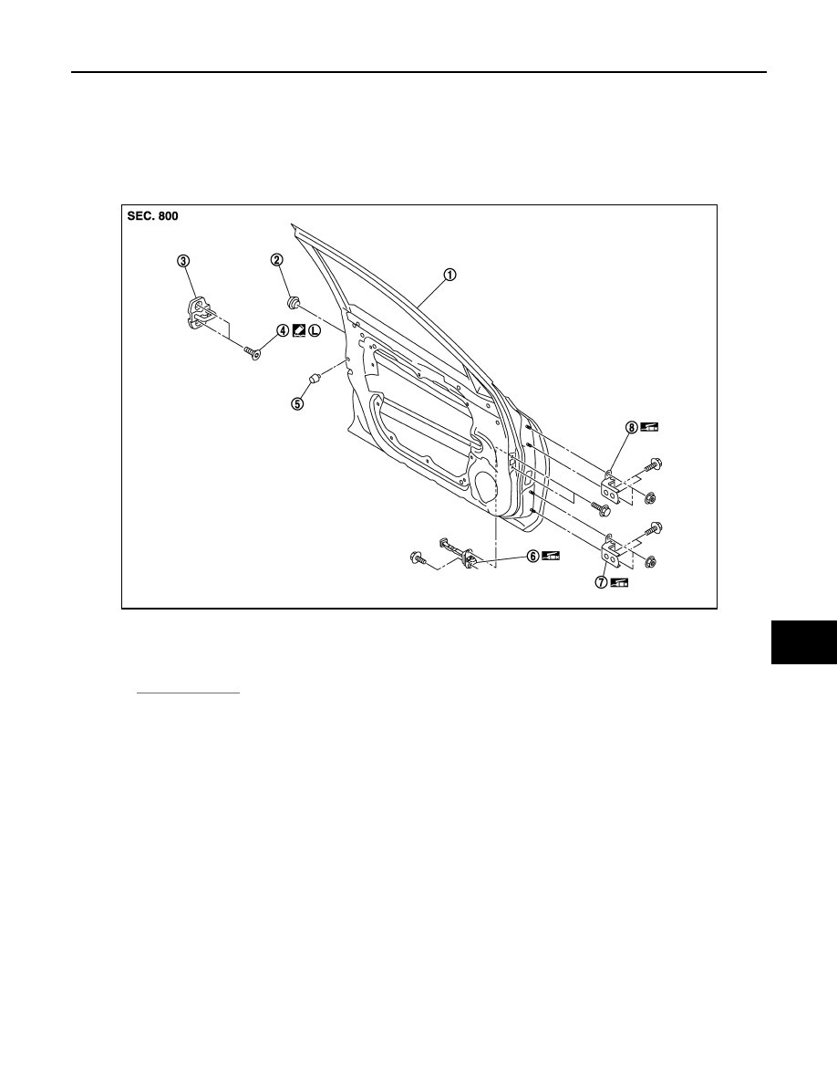
DOOR ASSEMBLY
DOOR ASSEMBLY : Exploded View
INFOID:0000000003556335
REMOVAL
ADJUSTMENT
1.
Front door panel
2.
Grommet
3.
Door striker
4.
TORX bolt
5.
Bumper rubber
6.
Door check link
7.
Door hinge (lower)
8.
Door hinge (upper)
Refer to
JMKIA2049ZZ
Нет комментариевНе стесняйтесь поделиться с нами вашим ценным мнением.
Текст