Infiniti EX35. Manual — part 926
HAC-100
< COMPONENT DIAGNOSIS >
[AUTOMATIC AIR CONDITIONER]
INTAKE SENSOR
INTAKE SENSOR
Description
INFOID:0000000003545638
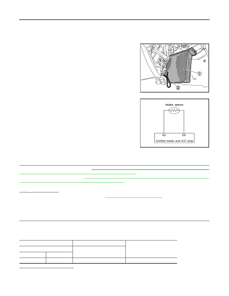
Intake Sensor
The intake sensor (2) is located on the evaporator. It converts air
temperature after it passes through the evaporator (1) into a resis-
tance value which is then input to the unified meter and A/C amp.
Intake Sensor Circuit
Component Function Check
INFOID:0000000003545639
1.
PERFORM SELF-DIAGNOSIS STEP-2
Perform self-diagnosis STEP-2. Refer to
HAC-57, "WITHOUT LEFT AND RIGHT VENTILATION TEMPERA-
TURE SEPARATELY CONTROL SYSTEM : Diagnosis Description"
(Without left and right ventilation tempera-
ture separately control system) or
HAC-63, "WITH LEFT AND RIGHT VENTILATION TEMPERATURE
SEPARATELY CONTROL SYSTEM : Diagnosis Description"
(With left and right ventilation temperature sepa-
rately control system), see Nos. 1 to 2.
24 or
−
24 is displayed.
YES
>> Go to Diagnosis Procedure. Refer to
HAC-100, "Diagnosis Procedure"
NO
>> END.
Diagnosis Procedure
INFOID:0000000003545640
1.
CHECK VOLTAGE BETWEEN INTAKE SENSOR AND GROUND
1.
Disconnect intake sensor connector.
2.
Turn ignition switch ON.
3.
Check voltage between intake sensor harness connector and ground.
Is the inspection result normal?
YES
>> GO TO 2.
NO
>> GO TO 4.
JPIIA0650ZZ
RJIA4104E
(+)
(
−
)
Voltage
Intake sensor
—
Connector
Terminal
M77
1
Ground
Approx. 5 V

INTAKE SENSOR
HAC-101
< COMPONENT DIAGNOSIS >
[AUTOMATIC AIR CONDITIONER]
C
D
E
F
G
H
J
K
L
M
A
B
HAC
N
O
P
2.
CHECK CIRCUIT CONTINUITY BETWEEN INTAKE SENSOR AND UNIFIED METER AND A/C AMP.
1.
Turn ignition switch OFF.
2.
Disconnect unified meter and A/C amp. connector.
3.
Check continuity between intake sensor harness connector and unified meter and A/C amp. harness con-
nector.
Is the inspection result normal?
YES
>> GO TO 3.
NO
>> Repair harness or connector.
3.
CHECK INTAKE SENSOR
Check intake sensor. Refer to
HAC-101, "Component Inspection"
Is the inspection result normal?
YES
>> Replace unified meter and A/C amp.
NO
>> Replace intake sensor.
4.
CHECK CIRCUIT CONTINUITY BETWEEN INTAKE SENSOR AND UNIFIED METER AND A/C AMP.
1.
Turn ignition switch OFF.
2.
Disconnect unified meter and A/C amp. connector.
3.
Check continuity between intake sensor harness connector and unified meter and A/C amp. harness con-
nector.
4.
Check continuity between intake sensor harness connector and ground.
Is the inspection result normal?
YES
>> Replace unified meter and A/C amp.
NO
>> Repair harness or connector.
Component Inspection
INFOID:0000000003545641
1.
CHECK INTAKE SENSOR
1.
Turn ignition switch OFF.
2.
Disconnect intake sensor connector.
3.
Check resistance between intake sensor terminals.
Intake sensor
Unified meter and A/C amp.
Continuity
Connector
Terminal
Connector
Terminal
M77
2
M67
59
Existed
Intake sensor
Unified meter and A/C amp.
Continuity
Connector
Terminal
Connector
Terminal
M77
1
M67
43
Existed
Intake sensor
—
Continuity
Connector
Terminal
M77
1
Ground
Not existed
HAC-102
< COMPONENT DIAGNOSIS >
[AUTOMATIC AIR CONDITIONER]
INTAKE SENSOR
Is the inspection result normal?
YES
>> END.
NO
>> Replace intake sensor.
Terminal
Condition
Resistance k
Ω
Temperature
°
C (
°
F)
1
2
−
15 (5)
12.34
−
10 (14)
9.62
−
5 (23)
7.56
0 (32)
6.00
5 (41)
4.80
10 (50)
3.87
15 (59)
3.15
20 (68)
2.57
25 (77)
2.12
30 (86)
1.76
35 (95)
1.47
40 (104)
1.23
45 (113)
1.04
POWER SUPPLY AND GROUND CIRCUIT FOR AUTO AMP.
HAC-103
< COMPONENT DIAGNOSIS >
[AUTOMATIC AIR CONDITIONER]
C
D
E
F
G
H
J
K
L
M
A
B
HAC
N
O
P
POWER SUPPLY AND GROUND CIRCUIT FOR AUTO AMP.
Description
INFOID:0000000003545642
COMPONENT DESCRIPTION
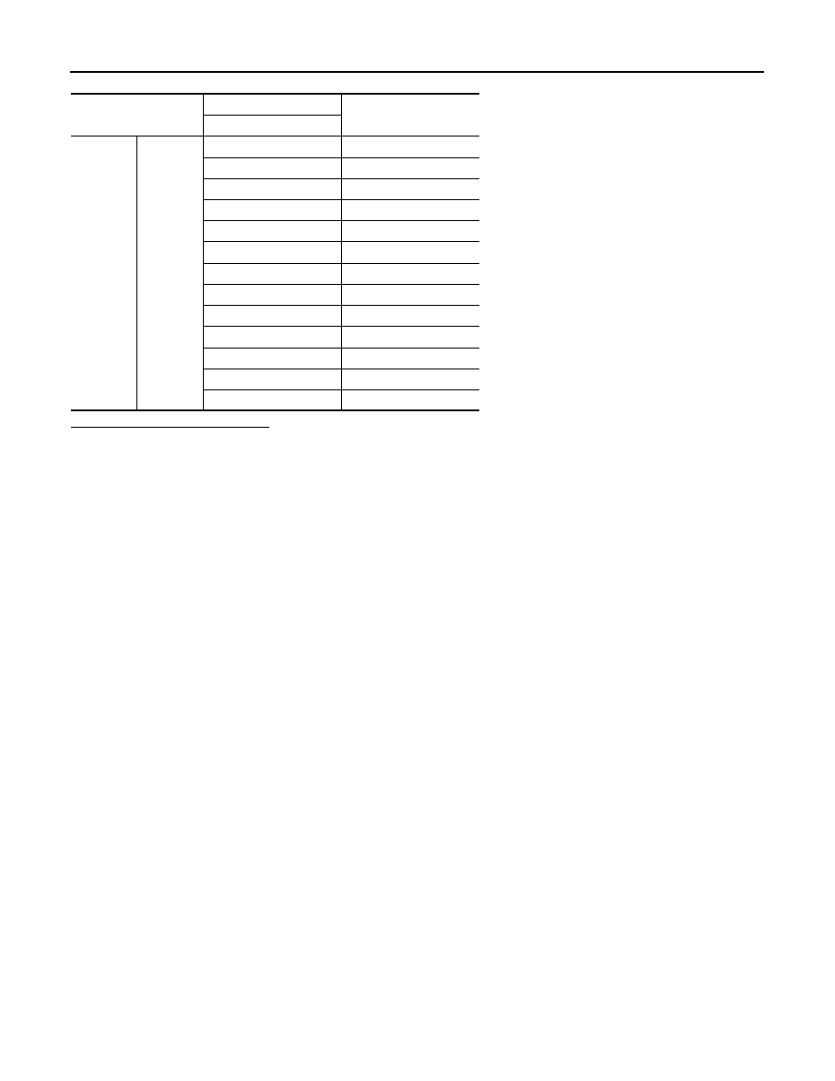
Unified Meter and A/C Amp. (Automatic Amplifier)
The unified meter and A/C amp. (1) has a built-in microcomputer
which processes information sent from various sensors needed for
air conditioner operation. The air mix door motor(s), mode door
motor, intake door motor, blower motor and compressor are then
controlled.
When the various switches and temperature control dial are oper-
ated, data is input to the unified meter and A/C amp. from the AV
control unit using CAN communication.
Self-diagnosis functions are also built into unified meter and A/C
amp. to provide quick check of malfunctions in the auto air condi-
tioner system.
Power Supply and Ground Circuit for Unified Meter and A/C Amp.
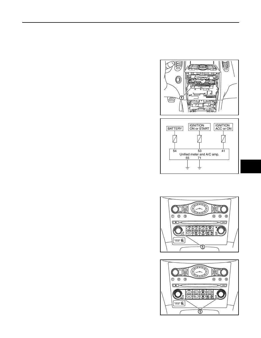
Potentio Temperature Control (PTC)
The PTC (1) is built into the preset switch. It can be set at an interval of 0.5
°
C (1.0
°
F) in the 18
°
C (60
°
F) to
32
°
C (90
°
F) temperature range by turning temperature control dial. The set temperature is displayed.
Without left and right ventilation temperature separately system
With left and right ventilation temperature separately system
JSIIA1072ZZ
RJIA4049E
JSIIA0135ZZ
JSIIA0020GB
Нет комментариевНе стесняйтесь поделиться с нами вашим ценным мнением.
Текст