Infiniti EX35. Manual — part 927

HAC-104
< COMPONENT DIAGNOSIS >
[AUTOMATIC AIR CONDITIONER]
POWER SUPPLY AND GROUND CIRCUIT FOR AUTO AMP.
Component Function Check
INFOID:0000000003545643
1.
CONFIRM SYMPTOM BY PERFORMING THE FOLLOWING OPERATIONAL CHECK
1.
Press AUTO switch.
2.
Display should indicate AUTO. Confirm that the compressor clutch engages (sound or visual inspection).
(Discharge air and blower speed depend on ambient, in-vehicle and set temperatures.)
Does magnet clutch engaged?
YES
>> END.
NO
>> Go to Diagnosis Procedure. Refer to
HAC-104, "Diagnosis Procedure"
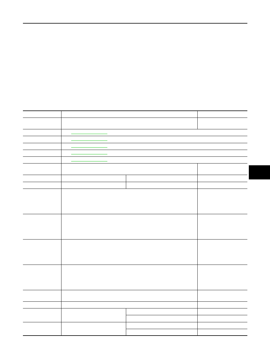
Diagnosis Procedure
INFOID:0000000003545644
1.
CHECK POWER SUPPLY CIRCUIT FOR UNIFIED METER AND A/C AMP.
1.
Disconnect unified meter and A/C amp. connector.
2.
Check voltage between unified meter and A/C amp. harness connector and ground.
Is the inspection result normal?
YES
>> GO TO 3.
NO
>> GO TO 2.
2.
CHECK FUSE
Check 10A fuses [Nos. 3, 6 and 19, located in the fuse block (J/B)]. Refer to
PG-98, "Fuse, Connector and Ter-
.
Is the inspection result normal?
YES
>> Check harness for open circuit. Repair or replace if necessary.
NO
>> Check harness for short circuit and replace fuse.
3.
CHECK GROUND CIRCUIT FOR UNIFIED METER AND A/C AMP.
1.
Turn ignition switch OFF.
2.
Check continuity between unified meter and A/C amp. harness connector and ground.
Is the inspection result normal?
YES
>> GO TO 4.
NO
>> Repair harness or connector.
4.
CHECK PRESET SWITCH
Check preset switch. Refer to
(BASE AUDIO WITHOUT NAVIGATION),
(BOSE AUDIO WITHOUT NAVIGATION) or
(BOSE AUDIO WITH
NAVIGATION).
Is the inspection result normal?
YES
>> Replace unified meter and A/C amp.
NO
>> Repair or replace malfunctioning part(s).
(+)
(
−
)
Voltage
Unified meter and A/C amp.
—
Ignition switch position
Connector
Terminal
OFF
ACC
ON
M67
41
Ground
Approx. 0 V
Battery voltage
Battery voltage
53
Approx. 0 V
Approx. 0 V
Battery voltage
54
Battery voltage
Battery voltage
Battery voltage
Unified meter and A/C amp.
—
Continuity
Connector
Terminal
M67
55
Ground
Existed
71
ECM
HAC-105
< ECU DIAGNOSIS >
[AUTOMATIC AIR CONDITIONER]
C
D
E
F
G
H
J
K
L
M
A
B
HAC
N
O
P
ECU DIAGNOSIS
ECM
Reference Value
INFOID:0000000003597535
VALUES ON THE DIAGNOSIS TOOL
NOTE:
• Specification data are reference values.
• Specification data are output/input values which are detected or supplied by the ECM at the connector.
* Specification data may not be directly related to their components signals/values/operations.
i.e. Adjust ignition timing with a timing light before monitoring IGN TIMING, because the monitor may show
the specification data in spite of the ignition timing not being adjusted to the specification data. this IGN TIM-
ING monitors the data calculated by the ECM according to the signals input from the camshaft position sen-
sor and other ignition timing related sensors.
CONSULT-III MONITOR ITEM
Monitor Item
Condition
Values/Status
ENG SPEED
• Run engine and compare CONSULT-III value with the tachometer indication.
Almost the same speed as
the tachometer indication
MAS A/F SE-B1
.
MAS A/F SE-B2
.
B/FUEL SCHDL
.
A/F ALPHA-B1
.
A/F ALPHA-B2
.
COOLAN TEMP/S
• Ignition switch: ON
Indicates engine coolant
temperature
A/F SEN1 (B1)
• Engine: After warming up
Maintaining engine speed at 2,000 rpm
Fluctuates around 2.2 V
A/F SEN1 (B2)
• Engine: After warming up
Maintaining engine speed at 2,000 rpm
Fluctuates around 2.2 V
HO2S2 (B1)
• Revving engine from idle up to 3,000 rpm quickly after the following conditions
are met.
- Engine: After warming up
- After keeping engine speed between 3,500 and 4,000 rpm for 1 minute and at
idle for 1 minute under no load
0 - 0.3V
←→
Approx. 0.6 -
1.0V
HO2S2 (B2)
• Revving engine from idle up to 3,000 rpm quickly after the following conditions
are met.
- Engine: After warming up
- After keeping engine speed between 3,500 and 4,000 rpm for 1 minute and at
idle for 1 minute under no load
0 - 0.3V
←→
Approx. 0.6 -
1.0V
HO2S2 MNTR (B1)
• Revving engine from idle up to 3,000 rpm quickly after the following conditions
are met.
- Engine: After warming up
- After keeping engine speed between 3,500 and 4,000 rpm for 1 minute and at
idle for 1 minute under no load
LEAN
←→
RICH
HO2S2 MNTR (B2)
• Revving engine from idle up to 3,000 rpm quickly after the following conditions
are met.
- Engine: After warming up
- After keeping engine speed between 3,500 and 4,000 rpm for 1 minute and at
idle for 1 minute under no load
LEAN
←→
RICH
VHCL SPEED SE
• Turn drive wheels and compare CONSULT-III value with the speedometer indi-
cation.
Almost the same speed as
speedometer indication
BATTERY VOLT
• Ignition switch: ON (Engine stopped)
11 - 14V
ACCEL SEN 1
• Ignition switch: ON
(Engine stopped)
Accelerator pedal: Fully released
0.5 - 1.0V
Accelerator pedal: Fully depressed
4.2 - 4.8V
ACCEL SEN 2*
1
• Ignition switch: ON
(Engine stopped)
Accelerator pedal: Fully released
0.5 - 1.0V
Accelerator pedal: Fully depressed
4.2 - 4.8V

HAC-106
< ECU DIAGNOSIS >
[AUTOMATIC AIR CONDITIONER]
ECM
TP SEN 1-B1
• Ignition switch: ON
(Engine stopped)
• Selector lever: D (A/T) or 1st (M/T)
Accelerator pedal: Fully released
More than 0.36V
Accelerator pedal: Fully depressed
Less than 4.75V
TP SEN 2-B1*
1
• Ignition switch: ON
(Engine stopped)
• Selector lever: D (A/T) or 1st (M/T)
Accelerator pedal: Fully released
More than 0.36V
Accelerator pedal: Fully depressed
Less than 4.75V
FUEL T/TMP SE
• Ignition switch: ON
Indicates fuel tank tempera-
ture
INT/A TEMP SE
• Ignition switch: ON
Indicates intake air temper-
ature
EVAP SYS PRES
• Ignition switch: ON
Approx. 1.8 - 4.8V
FUEL LEVEL SE
• Ignition switch: ON
Depending on fuel level of
fuel tank
START SIGNAL
• Ignition switch: ON
→
START
→
ON
OFF
→
ON
→
OFF
CLSD THL POS
• Ignition switch: ON
(Engine stopped)
Accelerator pedal: Fully released
ON
Accelerator pedal: Slightly depressed
OFF
AIR COND SIG
• Engine: After warming up, idle the
engine
Air conditioner switch: OFF
OFF
Air conditioner switch: ON
(Compressor operates.)
ON
P/N POSI SW
• Ignition switch: ON
Selector lever: P or N (A/T), Neutral (M/T)
ON
Selector lever: Except above
OFF
PW/ST SIGNAL
• Engine: After warming up, idle the
engine
Steering wheel: Not being turned
OFF
Steering wheel: Being turned
ON
LOAD SIGNAL
• Ignition switch: ON
Rear window defogger switch: ON
and/or
Lighting switch: 2nd position
ON
Rear window defogger switch and lighting
switch: OFF
OFF
IGNITION SW
• Ignition switch: ON
→
OFF
→
ON
ON
→
OFF
→
ON
HEATER FAN SW
• Engine: After warming up, idle the
engine
Heater fan switch: ON
ON
Heater fan switch: OFF
OFF
BRAKE SW
• Ignition switch: ON
Brake pedal: Fully released
OFF
Brake pedal: Slightly depressed
ON
INJ PULSE-B1
• Engine: After warming up
• Selector lever: P or N (A/T), Neu-
tral (M/T)
• Air conditioner switch: OFF
• No load
Idle
2.0 - 3.0 msec
2,000 rpm
1.9 - 2.9 msec
INJ PULSE-B2
• Engine: After warming up
• Selector lever: P or N (A/T), Neu-
tral (M/T)
• Air conditioner switch: OFF
• No load
Idle
2.0 - 3.0 msec
2,000 rpm
1.9 - 2.9 msec
IGN TIMING
• Engine: After warming up
• Selector lever: P or N (A/T), Neu-
tral (M/T)
• Air conditioner switch: OFF
• No load
Idle
6
°
- 16
°
BTDC (With 4WAS)
10
°
- 20
°
BTDC (Without
4WAS)
2,000 rpm
25
°
- 45
°
BTDC
CAL/LD VALUE
• Engine: After warming up
• Selector lever: P or N (A/T), Neu-
tral (M/T)
• Air conditioner switch: OFF
• No load
Idle
5% - 35%
2,500 rpm
5% - 35%
Monitor Item
Condition
Values/Status

ECM
HAC-107
< ECU DIAGNOSIS >
[AUTOMATIC AIR CONDITIONER]
C
D
E
F
G
H
J
K
L
M
A
B
HAC
N
O
P
MASS AIRFLOW
• Engine: After warming up
• Selector lever: P or N (A/T), Neu-
tral (M/T)
• Air conditioner switch: OFF
• No load
Idle
2.0 - 6.0 g·m/s
2,500 rpm
7.0 - 20.0 g·m/s
PURG VOL C/V
• Engine: After warming up
• Selector lever: P or N (A/T), Neu-
tral (M/T)
• Air conditioner switch: OFF
• No load
Idle
(Accelerator pedal: Not depressed even
slightly, after engine starting.)
0%
2,000 rpm
—
INT/V TIM (B1)
• Engine: After warming up
• Selector lever: P or N (A/T), Neu-
tral (M/T)
• Air conditioner switch: OFF
• No load
Idle
−
5
°
- 5
°
CA
2,000 rpm
Approx. 0
°
- 30
°
CA
INT/V TIM (B2)
• Engine: After warming up
• Selector lever: P or N (A/T), Neu-
tral (M/T)
• Air conditioner switch: OFF
• No load
Idle
−
5
°
- 5
°
CA
2,000 rpm
Approx. 0
°
- 30
°
CA
EXH/V TIM B1
• Engine: After warming up
• Selector lever: P or N (A/T), Neu-
tral (M/T)
• Air conditioner switch: OFF
• No load
Idle
−
5
°
- 5
°
CA
Around 2,500 rpm while the engine speed
is rising
Approx. 0
°
- 30
°
CA
EXH/V TIM B2
• Engine: After warming up
• Selector lever: P or N (A/T), Neu-
tral (M/T)
• Air conditioner switch: OFF
• No load
Idle
−
5
°
- 5
°
CA
Around 2,500 rpm while the engine speed
is rising
Approx. 0
°
- 30
°
CA
INT/V SOL (B1)
• Engine: After warming up
• Selector lever: P or N (A/T), Neu-
tral (M/T)
• Air conditioner switch: OFF
• No load
Idle
0% - 2%
2,000 rpm
Approx. 0% - 50%
INT/V SOL (B2)
• Engine: After warming up
• Selector lever: P or N (A/T), Neu-
tral (M/T)
• Air conditioner switch: OFF
• No load
Idle
0% - 2%
2,000 rpm
Approx. 0% - 50%
VTC DTY EX B1
• Engine: After warming up
• Selector lever: P or N (A/T), Neu-
tral (M/T)
• Air conditioner switch: OFF
• No load
Idle
0% - 2%
Around 2,500 rpm while the engine speed
is rising
Approx. 0% - 70%
VTC DTY EX B2
• Engine: After warming up
• Selector lever: P or N (A/T), Neu-
tral (M/T)
• Air conditioner switch: OFF
• No load
Idle
0% - 2%
Around 2,500 rpm while the engine speed
is rising
Approx. 0% - 70%
TP SEN 1-B2
• Ignition switch: ON
(Engine stopped)
• Selector lever: D (A/T) or 1st (M/T)
Accelerator pedal: Fully released
More than 0.36V
Accelerator pedal: Fully depressed
Less than 4.75V
TP SEN 2-B2*
1
• Ignition switch: ON
(Engine stopped)
• Selector lever: D (A/T) or 1st (M/T)
Accelerator pedal: Fully released
More than 0.36V
Accelerator pedal: Fully depressed
Less than 4.75V
AIR COND RLY
• Engine: After warming up, idle the
engine
Air conditioner switch: OFF
OFF
Air conditioner switch: ON
(Compressor operates)
ON
Monitor Item
Condition
Values/Status
Нет комментариевНе стесняйтесь поделиться с нами вашим ценным мнением.
Текст