Infiniti EX35. Manual — part 928

HAC-108
< ECU DIAGNOSIS >
[AUTOMATIC AIR CONDITIONER]
ECM
FUEL PUMP RLY
• For 1 seconds after turning ignition switch: ON
• Engine running or cranking
ON
• Except above
OFF
VENT CONT/V
• Ignition switch: ON
OFF
THRTL RELAY
• Ignition switch: ON
ON
HO2S2 HTR (B1)
• Engine speed: Below 3,600 rpm after the following conditions are met.
- Engine: After warming up
- Keeping the engine speed between 3,500 and 4,000 rpm for 1 minute and at
idle for 1 minute under no load
ON
• Engine speed: Above 3,600 rpm
OFF
HO2S2 HTR (B2)
• Engine speed: Below 3,600 rpm after the following conditions are met.
- Engine: After warming up
- Keeping the engine speed between 3,500 and 4,000 rpm for 1 minute and at
idle for 1 minute under no load
ON
• Engine speed: Above 3,600 rpm
OFF
I/P PULLY SPD
• Vehicle speed: More than 20 km/h (12 MPH)
Almost the same speed as
the tachometer indication
VEHICLE SPEED
• Turn drive wheels and compare CONSULT-III value with the speedometer indi-
cation.
Almost the same speed as
the speedometer indication
IDL A/V LEARN
• Engine: Running
Idle air volume learning has not been per-
formed yet.
YET
Idle air volume learning has already been
performed successfully.
CMPLT
SNOW MODE SW
• Ignition switch: ON
Snow mode switch: ON
ON
Snow mode switch: OFF
OFF
ENG OIL TEMP
• Engine: After warming up
More than 70
°
C (158
°
F)
TRVL AFTER MIL
• Ignition switch: ON
Vehicle has traveled after MIL has turned
ON.
0 - 65,535 km
(0 - 40,723 miles)
A/F S1 HTR (B1)
• Engine: After warming up, idle the engine
(More than 140 seconds after starting engine)
4 - 100%
A/F S1 HTR (B2)
• Engine: After warming up, idle the engine
(More than 140 seconds after starting engine)
4 - 100%
AC PRESS SEN
• Engine: Idle
• Both A/C switch and blower fan switch: ON (Compressor operates)
1.0 - 4.0V
VHCL SPEED SE
• Turn drive wheels and compare CONSULT-III value with the speedometer indi-
cation.
Almost the same speed as
the speedometer indication
SET VHCL SPD
• Engine: Running
ASCD: Operating
The preset vehicle speed is
displayed
MAIN SW
• Ignition switch: ON
MAIN switch: Pressed
ON
MAIN switch: Released
OFF
CANCEL SW
• Ignition switch: ON
CANCEL switch: Pressed
ON
CANCEL switch: Released
OFF
RESUME/ACC SW
• Ignition switch: ON
RESUME/ACCELERATE switch:
Pressed
ON
RESUME/ACCELERATE switch: Re-
leased
OFF
SET SW
• Ignition switch: ON
SET/COAST switch: Pressed
ON
SET/COAST switch: Released
OFF
BRAKE SW1
(ICC/ASCD brake
switch)
• Ignition switch: ON
Brake pedal: Fully released
ON
Brake pedal: Slightly depressed
OFF
Monitor Item
Condition
Values/Status
ECM
HAC-109
< ECU DIAGNOSIS >
[AUTOMATIC AIR CONDITIONER]
C
D
E
F
G
H
J
K
L
M
A
B
HAC
N
O
P
*1: Accelerator pedal position sensor 2 signal and throttle position sensor 2 signal are converted by ECM internally. Thus, they differ
from ECM terminals voltage signal.
*2: Before measuring the terminal voltage, confirm that the battery is fully charged. Refer to
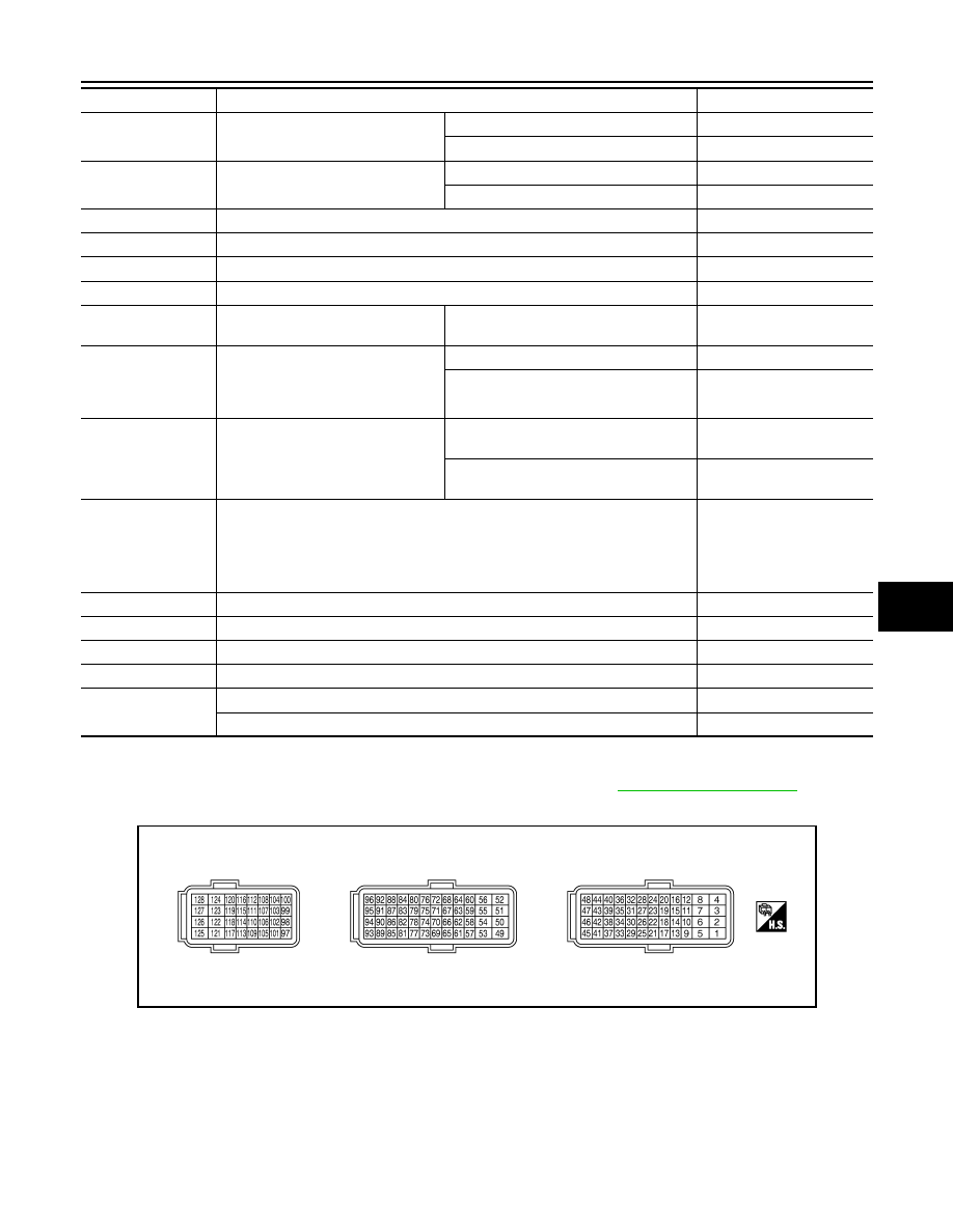
TERMINAL LAYOUT
PHYSICAL VALUES
NOTE:
• ECM is located behind the instrument assist lower panel. For this inspection, remove passenger side instru-
ment lower panel.
• Specification data are reference values and are measured between each terminal and ground.
• Pulse signal is measured by CONSULT-III.
CAUTION:
BRAKE SW2
(Stop lamp switch)
• Ignition switch: ON
Brake pedal: Fully released
OFF
Brake pedal: Slightly depressed
ON
DIST SW
• Ignition switch: ON
DISTANCE switch: Pressed
ON
DISTANCE switch: Released
OFF
VHCL SPD CUT
• Ignition switch: ON
NON
LO SPEED CUT
• Ignition switch: ON
NON
AT OD MONITOR
• Ignition switch: ON
OFF
AT OD CANCEL
• Ignition switch: ON
OFF
CRUISE LAMP
• Ignition switch: ON
MAIN switch: Pressed at the 1st time
→
at the 2nd time
ON
→
OFF
SET LAMP
• MAIN switch: ON
• When vehicle speed is between 40
km/h (25 MPH) and 144 km/h (89
MPH)
ASCD: Operating
ON
ASCD: Not operating
OFF
EXH V/T LEARN
• Engine: Running
Exhaust Valve Timing Control Learning
has not been performed yet.
YET
Exhaust Valve Timing Control Learning
has not been performed yet.
CMPLT
BAT CUR SEN
• Engine speed: Idle
• Battery: Fully charged*
2
• Selector lever: P or N (A/T), Neutral (M/T)
• Air conditioner switch: OFF
• No load
Approx. 2,600 - 3,500mV
ALT DUTY
• Engine: Idle
0 - 80%
A/F ADJ-B1
• Engine: Running
−
0.330 - 0.330
A/F ADJ-B2
• Engine: Running
−
0.330 - 0.330
FAN DUTY
• Engine: Running
0 - 100%
ALT DUTY SIG
• Power generation voltage variable control: Operating
ON
• Power generation voltage variable control: Not operating
OFF
Monitor Item
Condition
Values/Status
JMBIA0070ZZ

HAC-110
< ECU DIAGNOSIS >
[AUTOMATIC AIR CONDITIONER]
ECM
Do not use ECM ground terminals when measuring input/output voltage. Doing so may result in dam-
age to the ECMs transistor. Use a ground other than ECM terminals, such as the ground.
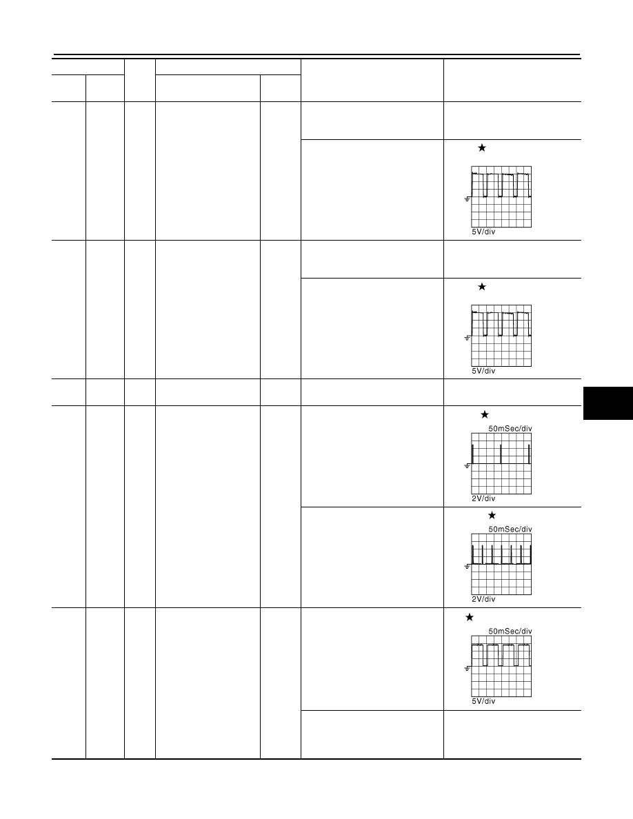
Terminal No.
Wire
color
Description
Condition
Value
(Approx.)
+
-–
Signal name
Input/
Output
1
Ground
W
A/F sensor 1 heater
(bank 1)
Output
[Engine is running]
• Warm-up condition
• Idle speed
(More than 140 seconds after
starting engine)
2.9 - 8.8V
2
Ground
G
Throttle control motor
(Open) (bank 1)
Output
[Ignition switch: ON]
• Engine stopped
• Selector lever: D (A/T) or 1st (M/
T)
• Accelerator pedal: Fully de-
pressed
0 - 14V
[Ignition switch: ON]
• Engine stopped
• Selector lever: D (A/T) or 1st (M/
T)
• Accelerator pedal: Fully re-
leased
0 - 14V
3
Ground
R
Throttle control motor re-
lay power supply (bank
1)
Input
[Ignition switch: ON]
BATTERY VOLTAGE
(11 - 14V)
4
Ground
BR
Throttle control motor
(Close) (bank 1)
Output
[Ignition switch: ON]
• Engine stopped
• Selector lever: D (A/T) or 1st (M/
T)
• Accelerator pedal: In the middle
of releasing operation
0 - 14V
5
Ground
GR
A/F sensor 1 heater
(bank 2)
Output
[Engine is running]
• Warm-up condition
• Idle speed
(More than 140 seconds after
starting engine)
2.9 - 8.8V
JMBIA0030GB
JMBIA0031GB
JMBIA0032GB
JMBIA0033GB
JMBIA0030GB
ECM
HAC-111
< ECU DIAGNOSIS >
[AUTOMATIC AIR CONDITIONER]
C
D
E
F
G
H
J
K
L
M
A
B
HAC
N
O
P
6
Ground
SB
Exhaust valve timing
control magnet retarder
(bank 1)
Output
[Engine is running]
• Warm-up condition
• Idle speed
BATTERY VOLTAGE
(11 - 14V)
[Engine is running]
• Warm-up condition
• Around 2,500 rpm while the en-
gine speed is rising
7 - 12V
7
Ground
Y
Exhaust valve timing
control magnet retarder
(bank 2)
Output
[Engine is running]
• Warm-up condition
• Idle speed
BATTERY VOLTAGE
(11 - 14V)
[Engine is running]
• Warm-up condition
• Around 2,500 rpm while the en-
gine speed is rising
7 - 12V
8
Ground
B
ECM ground
—
[Engine is running]
• Idle speed
Body ground
11
12
15
16
19
20
Ground
GR
L
V
G
SB
Y
Ignition signal No. 4
Ignition signal No. 3
Ignition signal No. 5
Ignition signal No. 2
Ignition signal No. 6
Ignition signal No. 1
Output
[Engine is running]
• Warm-up condition
• Idle speed
NOTE:
The pulse cycle changes de-
pending on rpm at idle
0 - 0.2V
[Engine is running]
• Warm-up condition
• Engine speed: 2,000 rpm
0.1 - 0.4V
17
Ground
P
Heated oxygen sensor 2
heater (bank 1)
Output
[Engine is running]
• Engine speed: Below 3,600 rpm
after the following conditions are
met
- Engine: after warming up
- Keeping the engine speed be-
tween 3,500 and 4,000 rpm for 1
minute and at idle for 1 minute
under no load
10V
[Ignition switch: ON]
• Engine stopped
[Engine is running]
• Engine speed: Above 3,600 rpm
BATTERY VOLTAGE
(11 - 14V)
Terminal No.
Wire
color
Description
Condition
Value
(Approx.)
+
-–
Signal name
Input/
Output
JMBIA0034GB
JMBIA0034GB
JMBIA0035GB
JMBIA0036GB
JMBIA0037GB
Нет комментариевНе стесняйтесь поделиться с нами вашим ценным мнением.
Текст