Infiniti EX35. Manual — part 193
AV
RGB SYNCHRONIZING SIGNAL CIRCUIT
AV-553
< COMPONENT DIAGNOSIS >
[BOSE AUDIO WITH NAVIGATION]
C
D
E
F
G
H
I
J
K
L
M
B
A
O
P
RGB SYNCHRONIZING SIGNAL CIRCUIT
Description
INFOID:0000000003160707
Transmit the RGB synchronizing signal to the display unit so as to synchronize the RGB image displayed with
AV control unit.
Diagnosis Procedure
INFOID:0000000003160708
1.
CHECK CONTINUITY RGB SYNCHRONIZING SIGNAL CIRCUIT
1.
Turn ignition switch OFF.
2.
Disconnect display unit connector and AV control unit connector.
3.
Check continuity between display unit harness connector and AV control unit harness connector.
4.
Check continuity between display unit harness connector and ground.
Is inspection result normal?
YES
>> GO TO 2.
NO
>> Repair harness or connector.
2.
CHECK RGB SYNCHRONIZING SIGNAL
1.
Connect display unit connector and AV control unit connector.
2.
Turn ignition switch ON.
3.
Check signal between display unit harness connector and ground.
Is inspection result normal?
YES
>> Replace display unit.
NO
>> Replace AV control unit.
Display unit
AV control unit
Continuity
Connector
Terminal
Connector
Terminal
M75
19
M88
65
Existed
Display unit
Ground
Continuity
Connector
Terminal
M75
19
Not existed
(+)
(
−
)
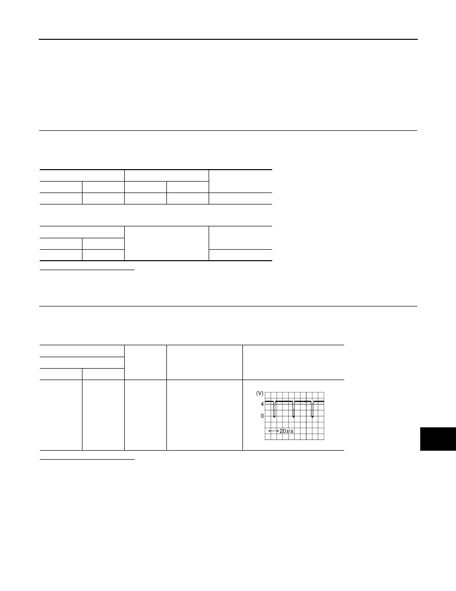
Condition
Reference value
Display unit
Connector
Terminal
M75
19
Ground
Start confirmation/adjust-
ment mode, and then dis-
play color bar by
selecting “Color Spec-
trum Bar” on DISPLAY
DIAGNOSIS screen.
SKIB3603E
AV-554
< COMPONENT DIAGNOSIS >
[BOSE AUDIO WITH NAVIGATION]
RGB AREA (YS) SIGNAL CIRCUIT
RGB AREA (YS) SIGNAL CIRCUIT
Description
INFOID:0000000003160709
Transmits the display area of RGB image displayed by AV control unit with RGB area (YS) signal to display
unit.
Diagnosis Procedure
INFOID:0000000003160710
1.
CHECK CONTINUITY RGB AREA (YS) SIGNAL CIRCUIT
1.
Turn ignition switch OFF.
2.
Disconnect display unit connector and AV control unit connector.
3.
Check continuity between display unit harness connector and AV control unit harness connector.
4.
Check continuity between display unit harness connector and ground.
Is inspection result normal?
YES
>> GO TO 2.
NO
>> Repair harness or connector.
2.
CHECK RGB SYNCHRONIZING SIGNAL
1.
Connect display unit connector and AV control unit connector.
2.
Turn ignition switch ON.
3.
Check signal between display unit harness connector and ground.
Is inspection result normal?
YES
>> Replace display unit.
NO
>> Replace AV control unit.
Display unit
AV control unit
Continuity
Connector
Terminal
Connector
Terminal
M75
9
M88
67
Existed
Display unit
Ground
Continuity
Connector
Terminal
M75
9
Not existed
(+)
(
−
)
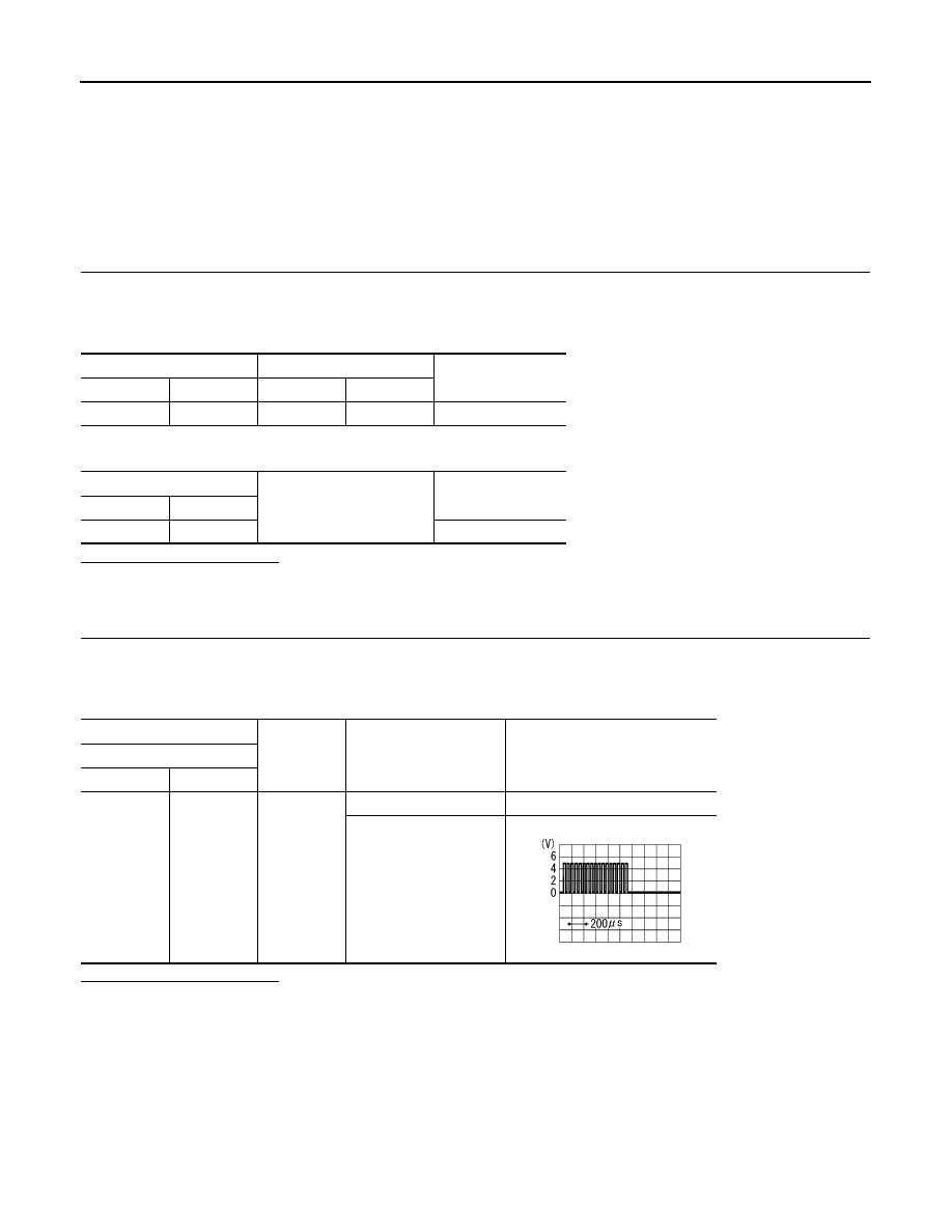
Condition
Reference value
(Approx.)
Display unit
Connector
Terminal
M75
9
Ground
At RGB image displayed
5.0 V
At AUX image displayed
PKIB4948J
AV
HORIZONTAL SYNCHRONIZING (HP) SIGNAL CIRCUIT
AV-555
< COMPONENT DIAGNOSIS >
[BOSE AUDIO WITH NAVIGATION]
C
D
E
F
G
H
I
J
K
L
M
B
A
O
P
HORIZONTAL SYNCHRONIZING (HP) SIGNAL CIRCUIT
Description
INFOID:0000000003160711
In composite image (AUX image, camera image), transmit the vertical synchronizing (VP) signal and horizon-
tal synchronizing (HP) signal from display unit to AV control unit so as to synchronize the RGB images dis-
played with AV control unit such as the image quality adjusting menu, etc.
Diagnosis Procedure
INFOID:0000000003160712
1.
CHECK CONTINUITY HORIZONTAL SYNCHRONIZING (HP) SIGNAL CIRCUIT
1.
Turn ignition switch OFF.
2.
Disconnect display unit connector and AV control unit connector.
3.
Check continuity between display unit harness connector and AV control unit harness connector.
4.
Check continuity between display unit harness connector and ground.
Is inspection result normal?
YES
>> GO TO 2.
NO
>> Repair harness or connector.
2.
CHECK HORIZONTAL SYNCHRONIZING (HP) SIGNAL
1.
Connect display unit connector and AV control unit connector.
2.
Turn ignition switch ON.
3.
Check signal between display unit harness connector and ground.
Is inspection result normal?
YES
>> Replace AV control unit.
NO
>> Replace Display unit.
Display unit
AV control unit
Continuity
Connector
Terminal
Connector
Terminal
M75
8
M88
68
Existed
Display unit
Ground
Continuity
Connector
Terminal
M75
8
Not existed
(+)
(
−
)
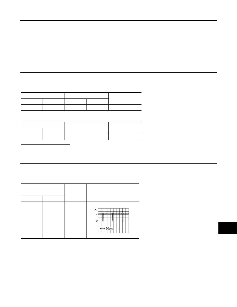
Reference value
Display unit
Connector
Terminal
M75
8
Ground
SKIB3603E
AV-556
< COMPONENT DIAGNOSIS >
[BOSE AUDIO WITH NAVIGATION]
VERTICAL SYNCHRONIZING (VP) SIGNAL CIRCUIT
VERTICAL SYNCHRONIZING (VP) SIGNAL CIRCUIT
Description
INFOID:0000000003513832
In composite image (AUX image, camera image), transmit the vertical synchronizing (VP) signal and horizon-
tal synchronizing (HP) signal from display unit to AV control unit so as to synchronize the RGB images dis-
played with AV control unit such as the image quality adjusting menu, etc.
Diagnosis Procedure
INFOID:0000000003160714
1.
CHECK CONTINUITY VERTICAL SYNCHRONIZING (VP) SIGNAL CIRCUIT
1.
Turn ignition switch OFF.
2.
Disconnect display unit connector and AV control unit connector.
3.
Check continuity between display unit harness connector and AV control unit harness connector.
4.
Check continuity between display unit harness connector and ground.
Is inspection result normal?
YES
>> GO TO 2.
NO
>> Repair harness or connector.
2.
CHECK VERTICAL SYNCHRONIZING (VP) SIGNAL
1.
Connect display unit connector and AV control unit connector.
2.
Turn ignition switch ON.
3.
Check signal between display unit harness connector and ground.
Is inspection result normal?
YES
>> Replace AV control unit.
NO
>> Replace Display unit.
Display unit
AV control unit
Continuity
Connector
Terminal
Connector
Terminal
M75
20
M88
69
Existed
Display unit
Ground
Continuity
Connector
Terminal
M75
20
Not existed
(+)
(
−
)
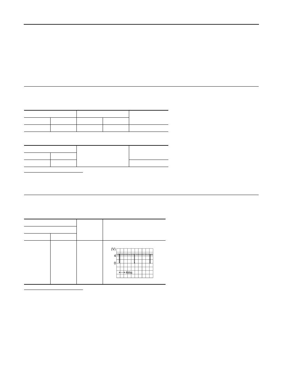
Reference value
Display unit
Connector
Terminal
M75
20
Ground
SKIB3598E
Нет комментариевНе стесняйтесь поделиться с нами вашим ценным мнением.
Текст