Infiniti EX35. Manual — part 194
AV
AUX IMAGE SIGNAL CIRCUIT
AV-557
< COMPONENT DIAGNOSIS >
[BOSE AUDIO WITH NAVIGATION]
C
D
E
F
G
H
I
J
K
L
M
B
A
O
P
AUX IMAGE SIGNAL CIRCUIT
Description
INFOID:0000000003160715
Transmits the image signal of external device from auxiliary input jacks to display unit.
Diagnosis Procedure
INFOID:0000000003160716
1.
CHECK CONTINUITY AUX IMAGE SIGNAL CIRCUIT
1.
Turn ignition switch OFF.
2.
Disconnect auxiliary input jacks connector and display unit connector.
3.
Check continuity between auxiliary input jacks harness connector and display unit harness connector.
4.
Check continuity between auxiliary input jacks harness connector and ground.
Is inspection result normal?
YES
>> GO TO 2.
NO
>> Repair harness or connector.
2.
CHECK AUX IMAGE SIGNAL
1.
Connect auxiliary input jacks connector and display unit connector.
2.
Turn ignition switch ON.
3.
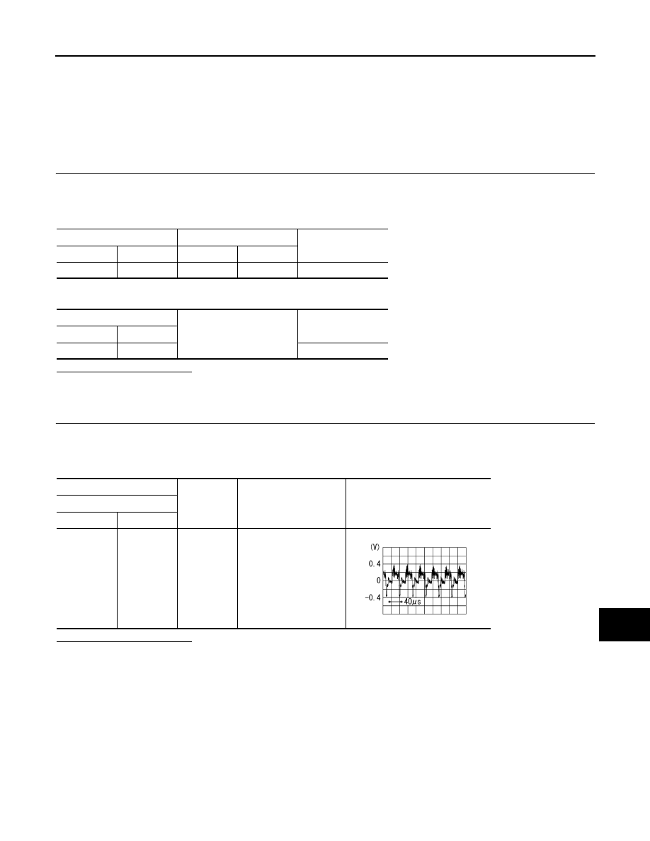
Check signal between auxiliary input jacks harness connector and ground.
Is inspection result normal?
YES
>> Replace display unit.
NO
>> Check that there is no malfunction in the external device.
Auxiliary input jacks
Display unit
Continuity
Connector
Terminal
Connector
Terminal
M154
7
M75
15
Existed
Auxiliary input jacks
Ground
Continuity
Connector
Terminal
M154
7
Not existed
(+)
(
−
)
Condition
Reference value
Auxiliary input jacks
Connector
Terminal
M154
7
Ground
At AUX image displayed
SKIB2251J

AV-558
< COMPONENT DIAGNOSIS >
[BOSE AUDIO WITH NAVIGATION]
MODE CHANGE SIGNAL CIRCUIT
MODE CHANGE SIGNAL CIRCUIT
Description
INFOID:0000000003533898
• AV control unit transmits the mode change signal to BOSE amp.
• Driver's Audio Stage controls the speaker's output characteristic by BOSE amp. so that the driver's seat is to
be the center of sounds.
Diagnosis Procedure
INFOID:0000000003533899
1.
CHECK CONTINUITY MODE CHANGE SIGNAL CIRCUIT
1.
Turn ignition switch OFF.
2.
Disconnect BOSE amp. connector and AV control unit connector.
3.
Check continuity between BOSE amp. harness connector and AV control unit harness connector.
4.
Check continuity between BOSE amp. harness connector and ground.
Is the inspection result normal?
YES
>> GO TO 2.
NO
>> Repair harness or connector.
2.
CHECK MODE CHANGE SIGNAL
1.
Connect BOSE amp. connector.
2.
Turn ignition switch ON.
3.
Check voltage between BOSE amp. harness connector and ground.
Is the inspection result normal?
YES
>> Replace AV control unit.
NO
>> Replace BOSE amp.
BOSE amp.
AV control unit
Continuity
Connector
Terminal
Connector
Terminal
B41
17
M87
44
Existed
BOSE amp.
Ground
Continuity
Connector
Terminal
B41
17
Not existed
(+)
(
−
)
Voltage
(Approx.)
BOSE amp.
Connector
Terminal
B41
17
Ground
8.5 V
AV
DISK EJECT SIGNAL CIRCUIT
AV-559
< COMPONENT DIAGNOSIS >
[BOSE AUDIO WITH NAVIGATION]
C
D
E
F
G
H
I
J
K
L
M
B
A
O
P
DISK EJECT SIGNAL CIRCUIT
Description
INFOID:0000000003160717
The eject signal is output to AV control unit when the eject switch of multifunction switch is pressed.
Diagnosis Procedure
INFOID:0000000003160718
1.
CHECK CONTINUITY CD EJECT SIGNAL CIRCUIT
1.
Turn ignition switch OFF.
2.
Disconnect multifunction switch connector and AV control unit connector.
3.
Check continuity between multifunction switch harness connector and AV control unit harness connector.
4.
Check continuity between multifunction switch harness connector and ground.
Is inspection result normal?
YES
>> GO TO 2.
NO
>> Repair harness or connector.
2.
CHECK AV CONTROL UNIT VOLTAGE
1.
Connect AV control unit connector.
2.
Turn ignition switch ON.
3.
Check voltage between AV control unit harness connector and ground.
Is inspection result normal?
YES
>> Replace preset switch.
NO
>> Replace AV control unit.
Multifunction switch
AV control unit
Continuity
Connector
Terminal
Connector
Terminal
M72
14
M89
85
Existed
Multifunction switch
Ground
Continuity
Connector
Terminal
M72
14
Not existed
(+)
(
−
)
Voltage
(Approx.)
AV control unit
Connector
Terminal
M89
85
Ground
3.3 V
AV-560
< COMPONENT DIAGNOSIS >
[BOSE AUDIO WITH NAVIGATION]
MICROPHONE SIGNAL CIRCUIT
MICROPHONE SIGNAL CIRCUIT
Description
INFOID:0000000003160719
Supply power from AV control unit to microphone. The microphone transmits the sound voice to the AV control
unit.
Diagnosis Procedure
INFOID:0000000003160720
1.
CHECK CONTINUITY BETWEEN AV CONTROL UNIT AND MICROPHONE CIRCUIT
1.
Turn ignition switch OFF.
2.
Disconnect AV control unit connector and microphone connector.
3.
Check continuity between AV control unit harness connector and microphone harness connector.
4.
Check continuity between AV control unit harness connector and ground.
Is inspection result normal?
YES
>> GO TO 2.
NO
>> Repair harness or connector.
2.
CHECK VOLTAGE MICROPHONE VCC
1.
Connect AV control unit connector.
2.
Turn ignition switch ON.
3.
Check voltage between AV control unit harness connector.
Is inspection result normal?
YES
>> GO TO 3.
NO
>> Replace AV control unit.
3.
CHECK MICROPHONE SIGNAL
1.
Turn ignition switch OFF.
2.
Connect microphone connector.
3.
Turn ignition switch ON.
4.
Check signal between AV control unit harness connector.
AV control unit
Microphone
Continuity
Connector
Terminals
Connector
Terminals
M87
26
R17
4
Existed
27
2
28
1
AV control unit
Ground
Continuity
Connector
Terminals
M87
26
Not existed
28
(+)
(
−
)
Voltage
(Approx.)
AV control unit
AV control unit
Connector
Terminal
Connector
Terminal
M87
26
M87
27
5.0 V
Нет комментариевНе стесняйтесь поделиться с нами вашим ценным мнением.
Текст