Infiniti EX35. Manual — part 192
AV
POWER SUPPLY AND GROUND CIRCUIT
AV-549
< COMPONENT DIAGNOSIS >
[BOSE AUDIO WITH NAVIGATION]
C
D
E
F
G
H
I
J
K
L
M
B
A
O
P
NO
>> Repair or replace sonar control unit power supply harness.
3.
CHECK GROUND CIRCUIT
1.
Turn ignition switch OFF.
2.
Disconnect sonar control unit connector.
3.
Check continuity between sonar control unit harness connector and ground.
Is the inspection result normal?
YES
>> INSPECTION END
NO
>> Repair or replace sonar control unit ground harness.
Sonar control unit
Ground
Continuity
Connector
Terminal
M47
24
Existed
AV-550
< COMPONENT DIAGNOSIS >
[BOSE AUDIO WITH NAVIGATION]
RGB (R: RED) SIGNAL CIRCUIT
RGB (R: RED) SIGNAL CIRCUIT
Description
INFOID:0000000003160701
Transmit the image displayed with AV control unit with RGB signal to the display unit.
Diagnosis Procedure
INFOID:0000000003160702
1.
CHECK CONTINUITY RGB (R: RED) SIGNAL CIRCUIT
1.
Turn ignition switch OFF.
2.
Disconnect display unit connector and AV control unit connector.
3.
Check continuity between display unit harness connector and AV control unit harness connector.
4.
Check continuity between display unit harness connector and ground.
Is inspection result normal?
YES
>> GO TO 2.
NO
>> Repair harness or connector.
2.
CHECK RGB (R: RED) SIGNAL
1.
Connect display unit connector and AV control unit connector.
2.
Turn ignition switch ON.
3.
Check signal between display unit harness connector and ground.
Is inspection result normal?
YES
>> Replace display unit.
NO
>> Replace AV control unit.
Display unit
AV control unit
Continuity
Connector
Terminal
Connector
Terminal
M75
17
M88
61
Existed
Display unit
Ground
Continuity
Connector
Terminal
M75
17
Not existed
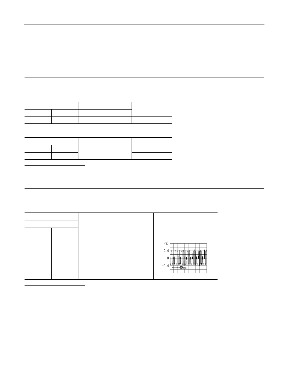
(+)
(
−
)
Condition
Reference value
Display unit
Connector
Terminal
M75
17
Ground
Start confirmation/adjust-
ment mode, and then dis-
play color bar by
selecting “Color Spec-
trum Bar” on DISPLAY
DIAGNOSIS screen.
SKIB2238J
AV
RGB (G: GREEN) SIGNAL CIRCUIT
AV-551
< COMPONENT DIAGNOSIS >
[BOSE AUDIO WITH NAVIGATION]
C
D
E
F
G
H
I
J
K
L
M
B
A
O
P
RGB (G: GREEN) SIGNAL CIRCUIT
Description
INFOID:0000000003513830
Transmit the image displayed with AV control unit with RGB signal to the display unit.
Diagnosis Procedure
INFOID:0000000003160704
1.
CHECK CONTINUITY RGB (G: GREEN) SIGNAL CIRCUIT
1.
Turn ignition switch OFF.
2.
Disconnect display unit connector and AV control unit connector.
3.
Check continuity between display unit harness connector and AV control unit harness connector.
4.
Check continuity between display unit harness connector and ground.
Is inspection result normal?
YES
>> GO TO 2.
NO
>> Repair harness or connector.
2.
CHECK RGB (G: GREEN) SIGNAL
1.
Connect display unit connector and AV control unit connector.
2.
Turn ignition switch ON.
3.
Check signal between display unit harness connector and ground.
Is inspection result normal?
YES
>> Replace display unit.
NO
>> Replace AV control unit.
Display unit
AV control unit
Continuity
Connector
Terminal
Connector
Terminal
M75
6
M88
62
Existed
Display unit
Ground
Continuity
Connector
Terminal
M75
6
Not existed
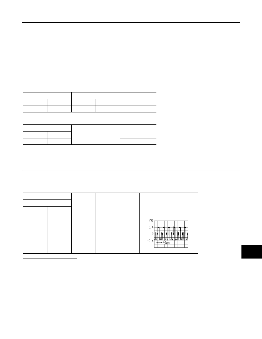
(+)
(
−
)
Condition
Reference value
Display unit
Connector
Terminal
M75
6
Ground
Start confirmation/adjust-
ment mode, and then dis-
play color bar by
selecting “Color Spec-
trum Bar” on DISPLAY
DIAGNOSIS screen.
SKIB2236J
AV-552
< COMPONENT DIAGNOSIS >
[BOSE AUDIO WITH NAVIGATION]
RGB (B: BLUE) SIGNAL CIRCUIT
RGB (B: BLUE) SIGNAL CIRCUIT
Description
INFOID:0000000003513831
Transmit the image displayed with AV control unit with RGB signal to the display unit.
Diagnosis Procedure
INFOID:0000000003160706
1.
CHECK CONTINUITY RGB (B: BLUE) SIGNAL CIRCUIT
1.
Turn ignition switch OFF.
2.
Disconnect display unit connector and AV control unit connector.
3.
Check continuity between display unit harness connector and AV control unit harness connector.
4.
Check continuity between display unit harness connector and ground.
Is inspection result normal?
YES
>> GO TO 2.
NO
>> Repair harness or connector.
2.
CHECK RGB (B: BLUE) SIGNAL
1.
Connect display unit connector and AV control unit connector.
2.
Turn ignition switch ON.
3.
Check signal between display unit harness connector and ground.
Is inspection result normal?
YES
>> Replace display unit.
NO
>> Replace AV control unit.
Display unit
AV control unit
Continuity
Connector
Terminal
Connector
Terminal
M75
18
M88
63
Existed
Display unit
Ground
Continuity
Connector
Terminal
M75
18
Not existed
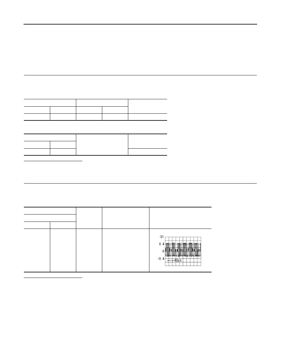
(+)
(
−
)
Condition
Reference value
Display unit
Connector
Terminal
M75
18
Ground
Start confirmation/adjust-
ment mode, and then dis-
play color bar by
selecting “Color Spec-
trum Bar” on DISPLAY
DIAGNOSIS screen.
SKIB2237J
Нет комментариевНе стесняйтесь поделиться с нами вашим ценным мнением.
Текст