Infiniti EX35. Manual — part 917
HAC-64
< FUNCTION DIAGNOSIS >
[AUTOMATIC AIR CONDITIONER]
DIAGNOSIS SYSTEM (UNIFIED METER & A/C AMP.)
- Inlet port memory function. Refer to
HAC-15, "WITH LEFT AND RIGHT VENTILATION TEMPERATURE
SEPARATELY CONTROL SYSTEM : Inlet Port Memory Function"
CONFORMATION METHOD
1.
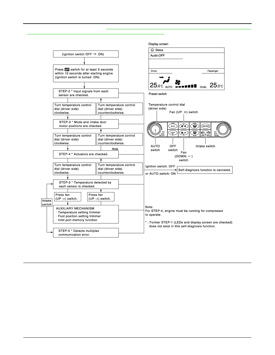
SET IN SELF-DIAGNOSIS MODE
1.
Turn ignition switch ON.
2.
Set in self-diagnosis mode as per the following. Press OFF switch for at least 5 seconds Within 10 sec-
onds after starting engine (ignition switch is turned ON).
NOTE:
• If battery voltage drops below 12 V during diagnosis STEP-3, door motor speed becomes slower and as a
result, the system may generate an error even when operation is normal. Start engine before performing this
diagnosis to avoid this.
• Former STEP-1 (indicators and display screen are checked) does not exist in this self-diagnosis function.
• OFF switch may not be recognized according to the timing of pressing it. Operate OFF switch after turning
the intake switch indicators (REC/FRE) ON.
>> GO TO 2.
2.
STEP-2: SENSOR AND DOOR MOTOR CIRCUITS ARE CHECKED FOR OPEN OR SHORT CIRCUIT
JSIIA1058GB
DIAGNOSIS SYSTEM (UNIFIED METER & A/C AMP.)
HAC-65
< FUNCTION DIAGNOSIS >
[AUTOMATIC AIR CONDITIONER]
C
D
E
F
G
H
J
K
L
M
A
B
HAC
N
O
P
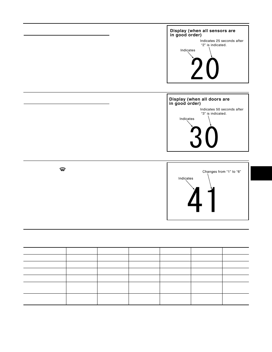
Does code No. 20 appear on the display?
YES
>> GO TO 3.
NO
>> GO TO 11.
3.
STEP-3: MODE DOOR AND INTAKE DOOR POSITIONS ARE CHECKED
Turn temperature control dial (driver side) clockwise.
Does code No. 30 appear on the display?
YES
>> GO TO 4.
NO
>> GO TO 12.
4.
STEP-4: OPERATION OF EACH DOOR MOTOR IS CHECKED
1.
Turn temperature control dial (driver side) clockwise.
2.
Press DEF (
) switch. Code No. of each door motor test is
indicated on the display.
>> GO TO 5.
5.
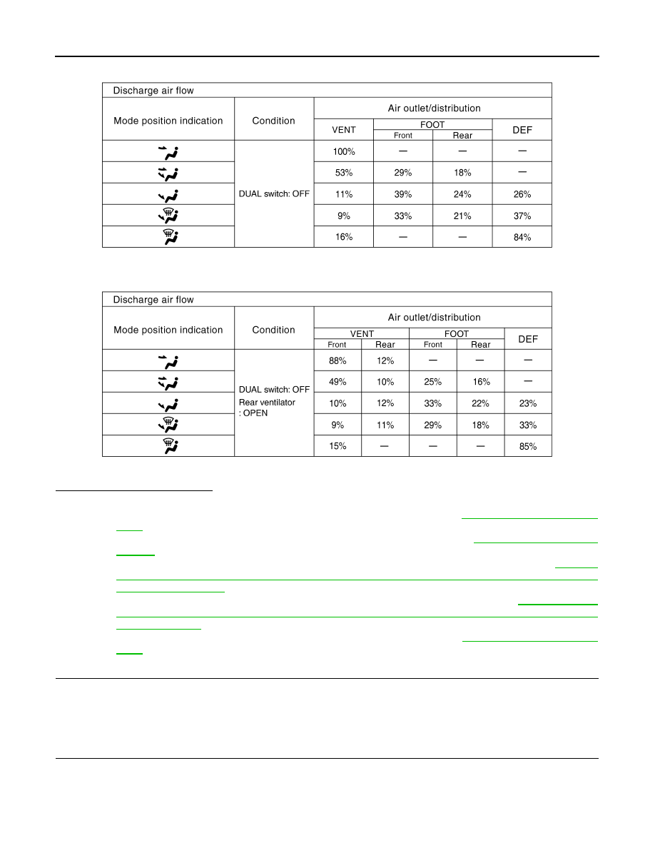
CHECK ACTUATORS
Refer to the following chart and check discharge air flow, air temperature, blower motor duty ratio and com-
pressor operation.
Checks must be made visually, by listening the sound, or by touching air outlets with hand, etc. for improper
operation.
SJIA1778E
SJIA1779E
SJIA1780E
Code No.
41
42
43
44
45
46
Mode door position
VENT
B/L 1
B/L 2
FOOT
D/F
DEF
Intake door position
REC
REC
20% FRE
FRE
FRE
FRE
Air mix door position
FULL COOL
FULL COOL
FULL HOT
FULL HOT
FULL HOT
FULL HOT
Blower motor duty ratio
37%
91%
65%
65%
65%
91%
Compressor (Magnet
clutch)
ON
ON
OFF
OFF
ON
ON
Electronic control valve
(ECV) duty ratio
100%
100%
0%
0%
50%
100%
HAC-66
< FUNCTION DIAGNOSIS >
[AUTOMATIC AIR CONDITIONER]
DIAGNOSIS SYSTEM (UNIFIED METER & A/C AMP.)
Without rear ventilation
With rear ventilation
Is this inspection result normal?
YES
>> GO TO 6.
NO-1
>> Air outlet does not change. Go to Mode Door Motor Circuit. Refer to
.
NO-2
>> Intake door does not change. Go to Intake Door Motor Circuit. Refer to
NO-3
>> Discharge air temperature does not change. Go to Air Mix Door Motor Circuit. Refer to
"WITH LEFT AND RIGHT VENTILATION TEMPERATURE SEPARATELY CONTROL SYSTEM :
Diagnosis Procedure"
NO-4
>> Blower motor operation is malfunctioning. Go to Blower Motor Circuit. Refer to
LEFT AND RIGHT VENTILATION TEMPERATURE SEPARATELY CONTROL SYSTEM : Diag-
nosis Procedure"
.
NO-5
>> Magnet clutch does not engage.Go to Magnet Clutch Circuit. Refer to
.
6.
STEP-5: TEMPERATURE OF EACH SENSOR IS CHECKED
1.
Turn temperature control dial (driver side) clockwise.
2.
Code No. 51 appears on the display.
>> GO TO 7.
7.
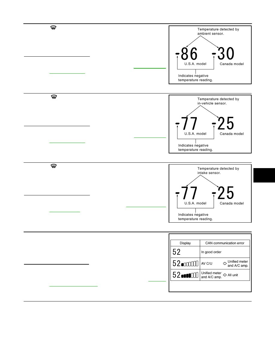
CHECK AMBIENT SENSOR
JSIIA0866GB
JSIIA0888GB
DIAGNOSIS SYSTEM (UNIFIED METER & A/C AMP.)
HAC-67
< FUNCTION DIAGNOSIS >
[AUTOMATIC AIR CONDITIONER]
C
D
E
F
G
H
J
K
L
M
A
B
HAC
N
O
P
Press DEF (
) switch one time. Temperature detected by ambient
sensor is indicated on the display.
NOTE:
Check sensor circuit first if the temperature indicated on the display
greatly differs from the actual temperature, and then check sensor.
Is this inspection result normal?
YES
>> GO TO 8.
NO
>> Go to Ambient Sensor Circuit. Refer to
.
8.
CHECK IN-VEHICLE SENSOR
Press DEF (
) switch for the second time. Temperature detected
by in-vehicle sensor is indicated on the display.
NOTE:
Check sensor circuit first if the temperature indicated on the display
greatly differs from the actual temperature, and then check sensor.
Is this inspection result normal?
YES
>> GO TO 9.
NO
>> Go to In-vehicle Sensor Circuit. Refer to
.
9.
CHECK INTAKE SENSOR
Press DEF (
) switch for the third time. Temperature detected by
intake sensor is indicated on the display.
NOTE:
Check sensor circuit first if the temperature indicated on the display
greatly differs from the actual temperature, and then check sensor.
Is this inspection result normal?
YES
>> GO TO 10.
NO
>> Go to Intake Sensor Circuit. Refer to
10.
CHECK CAN COMMUNICATION ERROR
1.
Press intake switch.
2.
CAN communication error between each unit that uses the uni-
fied meter and A/C amp. can be detected as self-diagnosis
results. (The display of each error will blink twice for 0.5 second
intervals if plural errors occur.)
Is the inspection result normal?
YES
>> INSPECTION END
NO
>> Go to CAN communication (Unified meter and A/C amp.
11.
CHECK MALFUNCTIONING SENSOR AND DOOR MOTOR
Refer to the following chart for malfunctioning code No.
(Corresponding code Nos. indicates 1 second each if two or more sensors and door motors malfunction.)
(Corresponding code Nos. indicates 0.5 second each if two door motors malfunction.)
PJIA0151E
PJIA0152E
PJIA0153E
JSIIA0138GB
Нет комментариевНе стесняйтесь поделиться с нами вашим ценным мнением.
Текст