Infiniti EX35. Manual — part 918
HAC-68
< FUNCTION DIAGNOSIS >
[AUTOMATIC AIR CONDITIONER]
DIAGNOSIS SYSTEM (UNIFIED METER & A/C AMP.)
*: Perform self-diagnosis STEP-2 under sunshine.
When performing indoors, aim a light (more than 60 W) at sunload sensor, otherwise code No. 25 indicates
despite that sunload sensor is functioning normally.
>> INSPECTION END
12.
CHECK MALFUNCTIONING DOOR MOTOR POSITION SWITCH
Mode and/or intake door motor PBR(s) is/are malfunctioning.
(Corresponding code Nos. indicates 1 second each if two or more mode or intake door motors malfunction.)
*1: The following display pattern will appear if mode door motor harness connector is disconnected.
31
→
32
→
Return to 31
*2: The following display pattern will appear if intake door motor harness connector is disconnected.
37
→
38
→
39
→
Return to 37
>> INSPECTION END
WITH LEFT AND RIGHT VENTILATION TEMPERATURE SEPARATELY CONTROL
Code No.
Malfunctioning sensor and door motor (Including circuits)
Reference
21 /
−
21
Ambient sensor
22 /
−
22
In-vehicle sensor
24 /
−
24
Intake sensor
HAC-100, "Diagnosis Procedure"
25 /
−
25
Sunload sensor
*
26 /
−
26
Air mix door motor PBR (Driver side)
HAC-75, "WITH LEFT AND RIGHT VENTILA-
TION TEMPERATURE SEPARATELY CON-
TROL SYSTEM : Diagnosis Procedure"
27 /
−
27
Air mix door motor PBR (Passenger side)
SJIA1781E
Code No.
*1 *2
Mode or intake door position
Reference
31
VENT
Mode door motor
32
DEF
37
FRE
Intake door motor
38
20% FRE
39
REC
SJIA1782E

DIAGNOSIS SYSTEM (UNIFIED METER & A/C AMP.)
HAC-69
< FUNCTION DIAGNOSIS >
[AUTOMATIC AIR CONDITIONER]
C
D
E
F
G
H
J
K
L
M
A
B
HAC
N
O
P
SYSTEM : CONSULT-III Function
INFOID:0000000003545588
CONSULT-III APPLICATION ITEMS
CONSULT-III can display each diagnosis item using the diagnosis test modes shown as per the following.
DATA MONITOR
Display Item List
System part
Check item, diagnosis mode
Description
ECM
Data monitor
Displays ECM input data in real time.
Monitor Item
Condition
Value/Status
IGNITION SW
Ignition switch OFF
→
ON
Off
→
On
HEATER FAN SW
Ignition switch ON
Blower fan motor switch ON
On
Blower fan motor switch OFF
Off
AIR COND SIG
Ignition switch ON
Compressor ON
On
Compressor OFF
Off
REFRIGERANT PRESSURE
SENSOR
• Engine is running
• Warm-up condition
• Both A/C switch and blower fan motor switch: ON (Compressor
operates)
1.0 - 4.0 V
HAC-70
< COMPONENT DIAGNOSIS >
[AUTOMATIC AIR CONDITIONER]
MODE DOOR MOTOR
COMPONENT DIAGNOSIS
MODE DOOR MOTOR
Description
INFOID:0000000003545603
COMPONENT DESCRIPTION
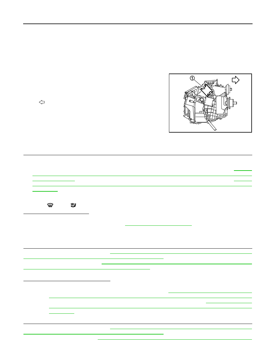
Mode Door Motor
The mode door motor (1) are attached to the heater & cooling unit
assembly. It rotates so that air is discharged from the outlet set by
the unified meter and A/C amp. Motor rotation is conveyed to a link
which activates the mode door.
Component Function Check
INFOID:0000000003545604
1.
CONFIRM SYMPTOM BY PERFORMING THE FOLLOWING OPERATIONAL CHECK
1.
Press MODE switch(es) and DEF switch.
2.
Each position indicator should change shape.
3.
Confirm that discharge air comes out according to the air distribution table at below. Refer to
"WITHOUT LEFT AND RIGHT VENTILATION TEMPERATURE SEPARATELY CONTROL SYSTEM :
System Description"
(Without left and right ventilation temperature separately control system) or
"WITH LEFT AND RIGHT VENTILATION TEMPERATURE SEPARATELY CONTROL SYSTEM : System
Description"
(With left and right ventilation temperature separately control system).
NOTE:
Confirm that the compressor clutch is engaged (Sound or visual inspection) and intake door position is at FRE
when DEF
or D/F
is selected.
Is the inspection result normal?
YES
>> END.
NO
>> Go to diagnosis procedure. Refer to
Diagnosis Procedure
INFOID:0000000003545605
1.
PERFORM SELF-DIAGNOSIS STEP-2
Perform self-diagnosis STEP-2. Refer to
HAC-57, "WITHOUT LEFT AND RIGHT VENTILATION TEMPERA-
TURE SEPARATELY CONTROL SYSTEM : Diagnosis Description"
(Without left and right ventilation tempera-
ture separately control system) or
HAC-63, "WITH LEFT AND RIGHT VENTILATION TEMPERATURE
SEPARATELY CONTROL SYSTEM : Diagnosis Description"
(With left and right ventilation temperature sepa-
rately control system), see Nos. 1 to 2.
Does code No. 20 appear on the display?
YES
>> GO TO 2.
NO
>> Go to appropriate malfunctioning sensor circuit. Refer to
HAC-57, "WITHOUT LEFT AND RIGHT
VENTILATION TEMPERATURE SEPARATELY CONTROL SYSTEM : Diagnosis Description"
(Without left and right ventilation temperature separately control system) or
AND RIGHT VENTILATION TEMPERATURE SEPARATELY CONTROL SYSTEM : Diagnosis
Description"
(With left and right ventilation temperature separately control system), see No. 11.
2.
PERFORM SELF-DIAGNOSIS STEP-3
Perform self-diagnosis STEP-3. Refer to
HAC-57, "WITHOUT LEFT AND RIGHT VENTILATION TEMPERA-
TURE SEPARATELY CONTROL SYSTEM : Diagnosis Description"
(Without left and right ventilation tempera-
ture separately control system)
HAC-63, "WITH LEFT AND RIGHT VENTILATION TEMPERATURE
:
Vehicle front
JSIIA0005GB
MODE DOOR MOTOR
HAC-71
< COMPONENT DIAGNOSIS >
[AUTOMATIC AIR CONDITIONER]
C
D
E
F
G
H
J
K
L
M
A
B
HAC
N
O
P
SEPARATELY CONTROL SYSTEM : Diagnosis Description"
(With left and right ventilation temperature sepa-
rately control system), see Nos. 1 to 3.
Does code No. 30 appear on the display?
YES
>> GO TO 6.
NO-1
>> Code No. 31 or 32 appear on the display: GO TO 3.
NO-2
>> Code No. 37, 38 or 39 appear on the display: Go to Intake Door Motor Circuit. Refer to
.
3.
CHECK POWER SUPPLY FOR MODE DOOR MOTOR
Check voltage between mode door motor harness connector and ground.
Is the inspection result normal?
YES
>> GO TO 4.
NO
>> Repair harness or connector.
4.
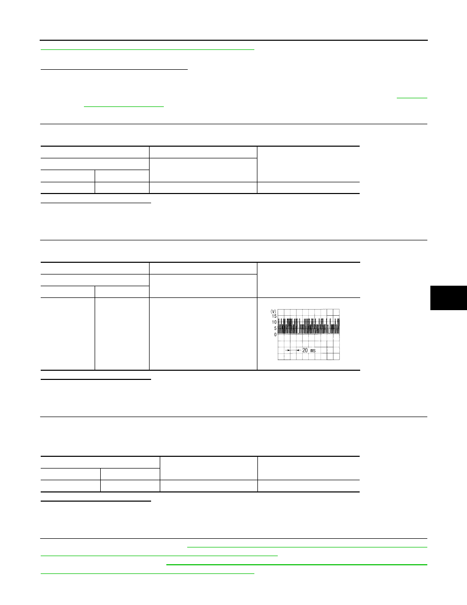
CHECK SIGNAL FOR MODE DOOR MOTOR
Confirm A/C LAN signal between mode door motor harness connector and ground using an oscilloscope.
Is the inspection result normal?
YES
>> GO TO 5.
NO
>> Repair harness or connector.
5.
CHECK MODE DOOR MOTOR GROUND CIRCUIT
1.
Turn ignition switch OFF.
2.
Disconnect mode door motor connector.
3.
Check continuity between mode door motor harness connector and ground.
Is the inspection result normal?
YES
>> Replace mode door motor.
NO
>> Repair harness or connector.
6.
PERFORM SELF-DIAGNOSIS STEP-4
Perform self-diagnosis STEP-4. Refer to
HAC-57, "WITHOUT LEFT AND RIGHT VENTILATION TEMPERA-
TURE SEPARATELY CONTROL SYSTEM : Diagnosis Description"
(Without left and right ventilation tempera-
ture separately control system)
HAC-63, "WITH LEFT AND RIGHT VENTILATION TEMPERATURE
SEPARATELY CONTROL SYSTEM : Diagnosis Description"
(With left and right ventilation temperature sepa-
rately control system), see Nos. 1 to 5.
(+)
(
−
)
Voltage
Mode door motor
—
Connector
Terminal
M253
1
Ground
Battery voltage
(+)
(
−
)
Voltage
Mode door motor
—
Connector
Terminal
M253
3
Ground
SJIA1453J
Mode door motor
—
Continuity
Connector
Terminal
M253
2
Ground
Existed
Нет комментариевНе стесняйтесь поделиться с нами вашим ценным мнением.
Текст