Infiniti EX35. Manual — part 916
HAC-60
< FUNCTION DIAGNOSIS >
[AUTOMATIC AIR CONDITIONER]
DIAGNOSIS SYSTEM (UNIFIED METER & A/C AMP.)
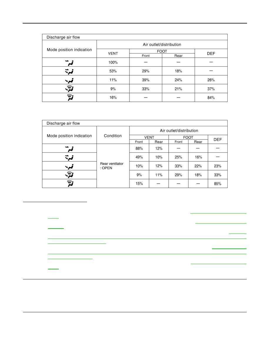
Without rear ventilation
With rear ventilation
Is the inspection result normal?
YES
>> GO TO 6.
NO-1
>> Air outlet does not change. Go to Mode Door Motor Circuit. Refer to
.
NO-2
>> Intake door does not change. Go to Intake Door Motor Circuit. Refer to
NO-3
>> Discharge air temperature does not change. Go to Air Mix Door Motor Circuit. Refer to
"WITHOUT LEFT AND RIGHT VENTILATION TEMPERATURE SEPARATELY CONTROL SYS-
TEM : Diagnosis Procedure"
NO-4
>> Blower motor operation is malfunctioning. Go to Blower Motor Circuit. Refer to
OUT LEFT AND RIGHT VENTILATION TEMPERATURE SEPARATELY CONTROL SYSTEM :
Diagnosis Procedure"
NO-5
>> Magnet clutch does not engage. Go to Magnet Clutch Circuit. Refer to
.
6.
STEP-5: TEMPERATURE OF EACH SENSOR IS CHECKED
1.
Turn temperature control dial clockwise.
2.
Code No. 51 appears on the display.
>> GO TO 7.
7.
CHECK AMBIENT SENSOR
JSIIA0242GB
JSIIA0893GB
DIAGNOSIS SYSTEM (UNIFIED METER & A/C AMP.)
HAC-61
< FUNCTION DIAGNOSIS >
[AUTOMATIC AIR CONDITIONER]
C
D
E
F
G
H
J
K
L
M
A
B
HAC
N
O
P
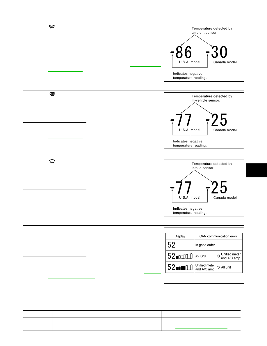
Press DEF (
) switch one time. Temperature detected by ambient
sensor is indicated on the display.
NOTE:
Check sensor circuit first if the temperature indicated on the display
greatly differs from the actual temperature, and then check sensor.
Is the inspection result normal?
YES
>> GO TO 8.
NO
>> Go to Ambient Sensor Circuit. Refer to
.
8.
CHECK IN-VEHICLE SENSOR
Press DEF (
) switch for the second time. Temperature detected
by in-vehicle sensor is indicated on the display.
NOTE:
Check sensor circuit first if the temperature indicated on the display
greatly differs from the actual temperature, and then check sensor.
Is the inspection result normal?
YES
>> GO TO 9.
NO
>> Go to In-vehicle Sensor Circuit. Refer to
.
9.
CHECK INTAKE SENSOR
Press DEF (
) switch for the third time. Temperature detected by
intake sensor is indicated on the display.
NOTE:
Check sensor circuit first if the temperature indicated on the display
greatly differs from the actual temperature, and then check sensor.
Is the inspection result normal?
YES
>> GO TO 10.
NO
>> Go to Intake Sensor Circuit. Refer to
10.
CHECK CAN COMMUNICATION ERROR
1.
Press intake switch.
2.
CAN communication error between each unit that uses the uni-
fied meter and A/C amp. can be detected as self-diagnosis
results. (The display of each error will blink twice for 0.5 second
intervals if plural errors occur.)
Is the inspection result normal?
YES
>> INSPECTION END
NO
>> Go to CAN communication (Unified meter and A/C amp.
11.
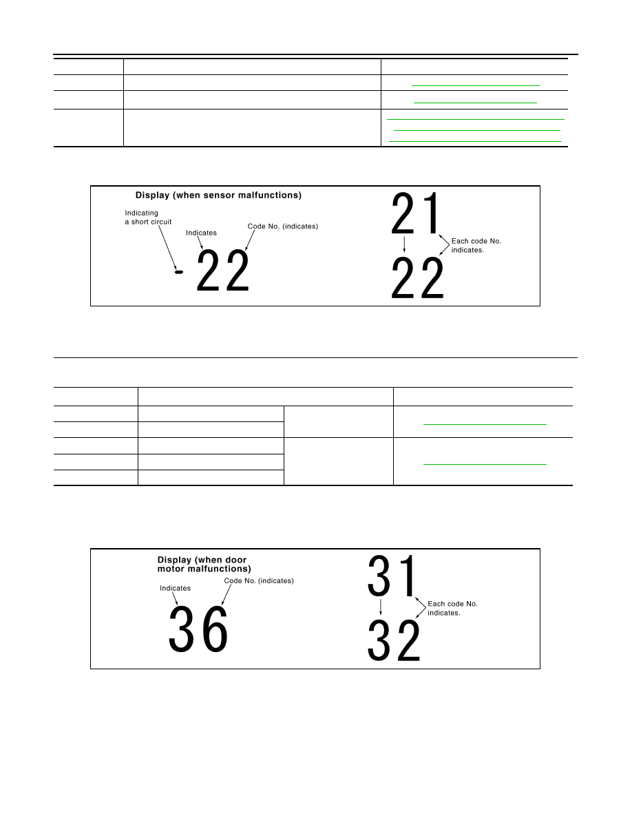
CHECK MALFUNCTIONING SENSOR AND DOOR MOTOR
Refer to the following chart for malfunctioning code No.
(Corresponding code Nos. indicates 1 second each if two or more sensors and door motor malfunction.)
PJIA0151E
PJIA0152E
PJIA0153E
JSIIA0138GB
Code No.
Malfunctioning sensor and door motor (Including circuits)
Reference
21 /
−
21
Ambient sensor
22 /
−
22
In-vehicle sensor
HAC-62
< FUNCTION DIAGNOSIS >
[AUTOMATIC AIR CONDITIONER]
DIAGNOSIS SYSTEM (UNIFIED METER & A/C AMP.)
*: Perform self-diagnosis STEP-2 under sunshine.
When performing indoors, aim a light (more than 60 W) at sunload sensor, otherwise code No. 25 indicates
despite that sunload sensor is functioning normally.
>> INSPECTION END
12.
CHECK MALFUNCTIONING DOOR MOTOR POSITION SWITCH
Mode and/or intake door motor PBR(s) is/are malfunctioning.
(Corresponding code Nos. indicates 1 second each if two or more mode or intake door motors malfunction.)
*1: The following display pattern will appear if mode door motor harness connector is disconnected.
31
→
32
→
Return to 31
*2: The following display pattern will appear if intake door motor harness connector is disconnected.
37
→
38
→
39
→
Return to 37
>> INSPECTION END
WITHOUT LEFT AND RIGHT VENTILATION TEMPERATURE SEPARATELY CON-
TROL SYSTEM : CONSULT-III Function
INFOID:0000000003545586
CONSULT-III APPLICATION ITEMS
CONSULT-III can display each diagnosis item using the diagnosis test modes shown as per the following.
24 /
−
24
Intake sensor
HAC-100, "Diagnosis Procedure"
25 /
−
25
Sunload sensor
*
26 /
−
26
Air mix door motor PBR
HAC-73, "WITHOUT LEFT AND RIGHT VEN-
TILATION TEMPERATURE SEPARATELY
CONTROL SYSTEM : Diagnosis Procedure"
Code No.
Malfunctioning sensor and door motor (Including circuits)
Reference
SJIA1781E
Code No.
*1 *2
Mode or intake door position
Reference
31
VENT
Mode door motor
32
DEF
37
FRE
Intake door motor
38
20% FRE
39
REC
SJIA1782E

DIAGNOSIS SYSTEM (UNIFIED METER & A/C AMP.)
HAC-63
< FUNCTION DIAGNOSIS >
[AUTOMATIC AIR CONDITIONER]
C
D
E
F
G
H
J
K
L
M
A
B
HAC
N
O
P
DATA MONITOR
Display Item List
WITH LEFT AND RIGHT VENTILATION TEMPERATURE SEPARATELY CON-
TROL SYSTEM
WITH LEFT AND RIGHT VENTILATION TEMPERATURE SEPARATELY CONTROL
SYSTEM : Diagnosis Description
INFOID:0000000003545587
SELF-DIAGNOSIS SYSTEM
The self-diagnosis system is built into the unified meter and A/C amp. to quickly locate the cause of malfunc-
tions.
SELF-DIAGNOSIS FUNCTION
• The self-diagnosis system diagnoses sensors, door motors, blower motor, etc. by system line. Refer to appli-
cable sections (items) for details. Shifting from normal control to the self-diagnosis system is accomplished
by starting the engine (turning the ignition switch ON) and pressing OFF switch for at least 5 seconds. The
OFF switch must be pressed within 10 seconds after starting the engine (ignition switch is turned ON). This
system is canceled by either pressing AUTO switch or turning the ignition switch OFF. Shifting from one step
is accomplished by means of turning temperature control dial (driver side), as required.
• Shifting from STEP-5 to AUXILIARY MECHANISM is accomplished by means of pressing fan (UP:+) switch.
- Temperature setting trimmer. Refer to
HAC-13, "WITH LEFT AND RIGHT VENTILATION TEMPERATURE
SEPARATELY CONTROL SYSTEM : Temperature Setting Trimmer"
- Foot position setting trimmer. Refer to
HAC-14, "WITH LEFT AND RIGHT VENTILATION TEMPERATURE
SEPARATELY CONTROL SYSTEM : Foot Position Setting Trimmer"
.
System part
Check item, diagnosis mode
Description
ECM
Data monitor
Displays ECM input data in real time.
Monitor Item
Condition
Value/Status
IGNITION SW
Ignition switch OFF
→
ON
Off
→
On
HEATER FAN SW
Ignition switch ON
Blower fan motor switch ON
On
Blower fan motor switch OFF
Off
AIR COND SIG
Ignition switch ON
Compressor ON
On
Compressor OFF
Off
REFRIGERANT PRESSURE
SENSOR
• Engine is running
• Warm-up condition
• Both A/C switch and blower fan motor switch: ON (Compressor
operates)
1.0 - 4.0 V
Нет комментариевНе стесняйтесь поделиться с нами вашим ценным мнением.
Текст