Infiniti EX35. Manual — part 707
AIR CLEANER AND AIR DUCT
EM-27
< ON-VEHICLE REPAIR >
C
D
E
F
G
H
I
J
K
L
M
A
EM
N
P
O
AIR CLEANER AND AIR DUCT
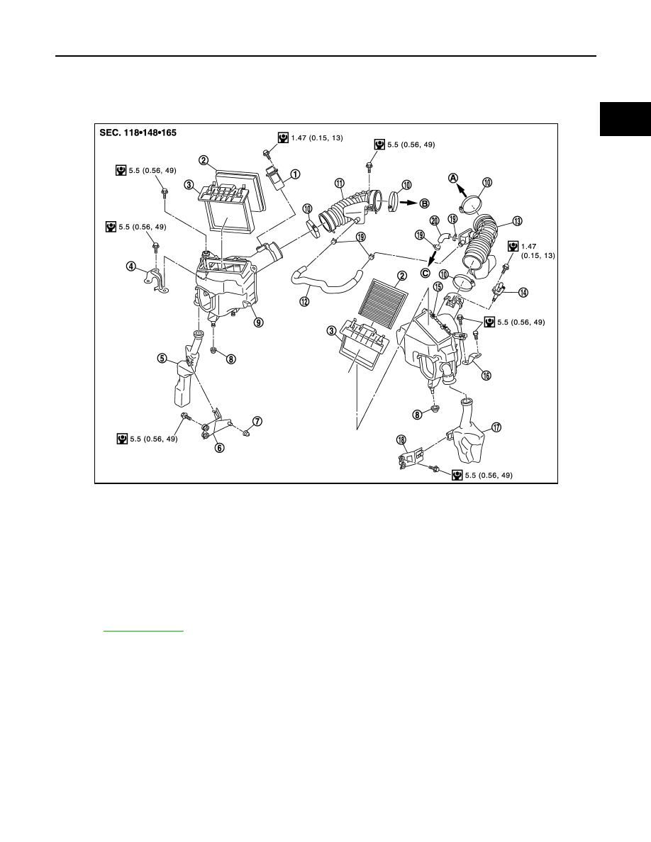
Exploded View
INFOID:0000000003139096
Removal and Installation
INFOID:0000000003139097
REMOVAL
1.
Disconnect mass air flow sensor harness connector.
2.
Disconnect PCV hose.
3.
Remove air cleaner case with mass air flow sensor and air duct, disconnecting each joints.
• Add marks as necessary for easier installation.
4.
Remove mass air flow sensor from air cleaner case, as necessary.
CAUTION:
Handle mass air flow sensor with the following cares.
• Never shock mass air flow sensor.
• Never disassemble mass air flow sensor.
1.
Mass air flow sensor (bank 1)
2.
Air cleaner filter
3.
Holder
4.
Bracket
5.
Resonator (RH)
6.
Bracket
7.
Grommet
8.
Grommet
9.
Air cleaner case (RH)
10. Clamp
11.
Air duct (RH)
12. PCV hose
13. Air duct (LH)
14. Mass air flow sensor (bank 2)
15. Air cleaner case (LH)
16. Bracket
17. Resonator (LH)
18. Bracket
19. Clamp
20. PCV hose
A.
To electric throttle control actuator
(bank 2)
B.
To electric throttle control actuator
(bank 1)
C.
To rocker cover (bank 2)
Refer to
for symbols in the figure.
JPBIA1824GB
EM-28
< ON-VEHICLE REPAIR >
AIR CLEANER AND AIR DUCT
• Never touch mass air flow sensor.
INSTALLATION
Note the following, and install in the reverse order of removal.
Inspection
INFOID:0000000003139098
INSPECTION AFTER REMOVAL
Inspect air duct and resonator assembly for crack or tear.
• If anything found, replace air duct and resonator assembly.

INTAKE MANIFOLD COLLECTOR
EM-29
< ON-VEHICLE REPAIR >
C
D
E
F
G
H
I
J
K
L
M
A
EM
N
P
O
INTAKE MANIFOLD COLLECTOR
Exploded View
INFOID:0000000003139099
Removal and Installation
INFOID:0000000003139100
REMOVAL
WARNING:
Never drain engine coolant when the engine is hot to avoid the danger of being scalded.
1.
Remove engine cover with power tool. Refer to
.
2.
Remove air cleaner case and air duct (RH and LH). Refer to
.
3.
Remove electric throttle control actuator as follows:
a.
Drain engine coolant, or when water hoses are disconnected, attach plug to prevent engine coolant leak-
age.
1.
EVAP canister purge control solenoid
valve
2.
Clamp
3.
EVAP hose
4.
EVAP hose
5.
Clamp
6.
Water hose
7.
Water hose
8.
Electric throttle control actuator
(bank1)
9.
Gasket
10. Intake manifold collector
11.
Gasket
12. Water hose
13. Water hose
14.
Electric throttle control actuator
(bank2)
15. EVAP hose
16. Water hose
17. EVAP tube assembly
18. EVAP hose
A.
To vacuum pipe
B.
To brake booster
C.
To heater pipe
D.
To water outlet (rear)
for symbols in the figure.
JPBIA1900GB
EM-30
< ON-VEHICLE REPAIR >
INTAKE MANIFOLD COLLECTOR
CAUTION:
• Perform this step when engine is cold.
• Never spill engine coolant on drive belt.
b.
Disconnect water hoses from electric throttle control actuator. When engine coolant is not drained from
radiator, attach plug to water hoses to prevent engine coolant leakage.
c.
Disconnect harness connector.
d.
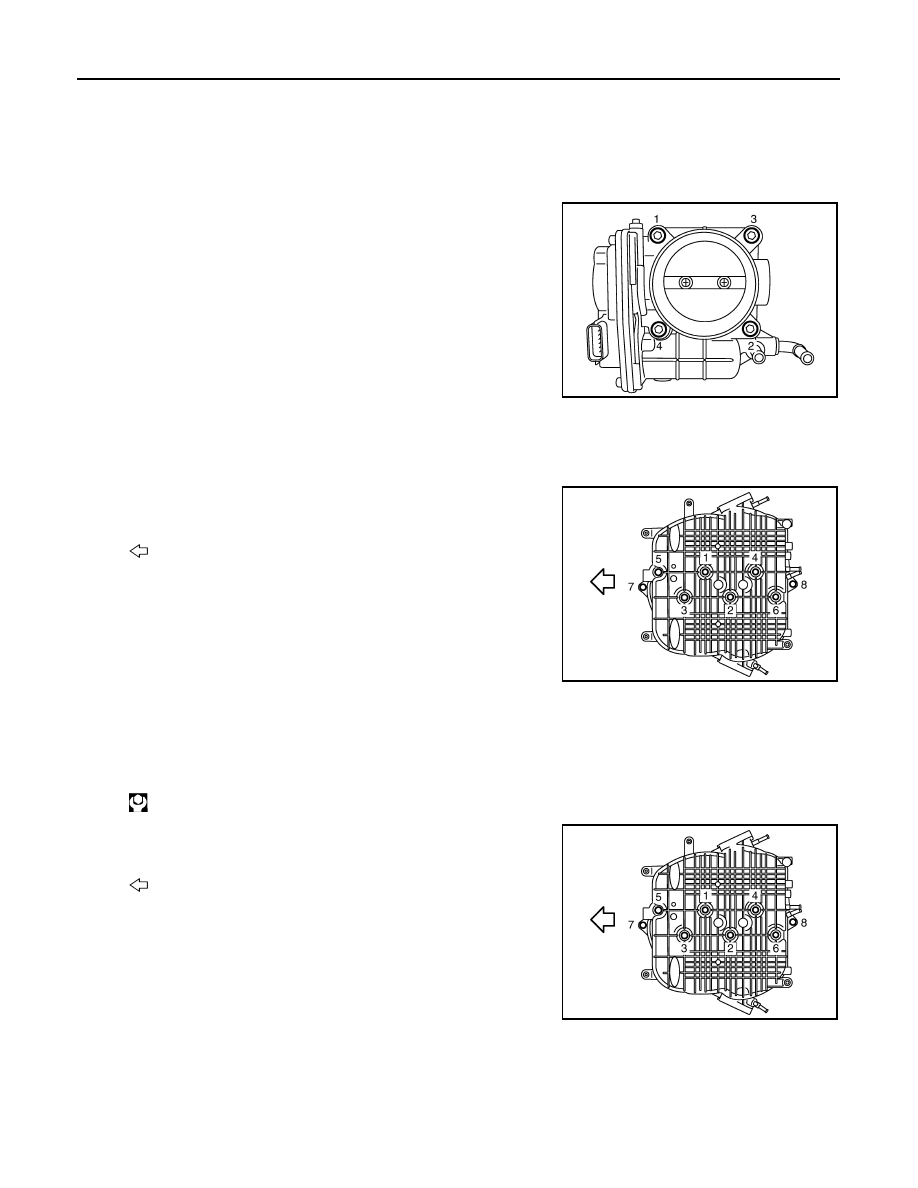
Loosen mounting bolts in reverse order as shown in the figure.
NOTE:
• When removing only intake manifold collector, move electric
throttle control actuator without disconnecting the water hose.
• The figure shows the electric throttle control actuator (bank 1)
viewed from the air duct side.
• Viewed from the air duct side, order of loosening mounting
bolts of electric throttle control actuator (bank 2) is the same
as that of the electric throttle control actuator (bank 1).
CAUTION:
Handle carefully to avoid any shock to electric throttle con-
trol actuator.
4.
Disconnect vacuum hose, PCV hose and EVAP hose from intake manifold collector.
5.
Remove EVAP canister purge volume control solenoid valve and EVAP tube assembly from intake mani-
fold collector.
6.
Loosen mounting bolts and nuts with power tool in the reverse
order as shown in the figure to remove intake manifold collector.
INSTALLATION
Note the following, and install in the reverse order of removal.
INTAKE MANIFOLD COLLECTOR
• If stud bolts were removed, install them and tighten to the specified torque below.
• Tighten mounting bolts and nuts in numerical order as shown in the
figure.
WATER HOSE
• Insert hose by 27 to 32 mm (1.06 to 1.26 in) from connector end.
• Clamp hose at location of 3 to 7 mm (0.12 to 0.28 in) from hose end.
ELECTRIC THROTTLE CONTROL ACTUATOR (BANK 1 AND BANK 2)
JPBIA0011ZZ
: Engine front
JPBIA0012ZZ
: 10.8 N·m (1.1 kg-m, 8 ft-lb)
: Engine front
JPBIA0012ZZ
Нет комментариевНе стесняйтесь поделиться с нами вашим ценным мнением.
Текст