Infiniti EX35. Manual — part 708

INTAKE MANIFOLD COLLECTOR
EM-31
< ON-VEHICLE REPAIR >
C
D
E
F
G
H
I
J
K
L
M
A
EM
N
P
O
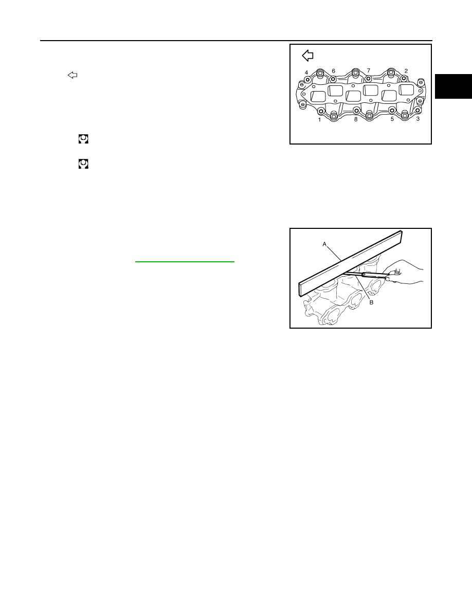
• Tighten in numerical order as shown in the figure.
NOTE:
• The figure shows the electric throttle control actuator (bank 1)
viewed from the air duct side.
• Viewed from the air duct side, order of tightening mounting bolts
of electric throttle control actuator (bank 2) is the same as that of
the electric throttle control actuator (bank 1).
• Perform the “Throttle Valve Closed Position Learning” when har-
ness connector of electric throttle control actuator is disconnected.
Refer to
EC-17, "THROTTLE VALVE CLOSED POSITION
.
• Perform the “Idle Air Volume Learning” and “Throttle Valve Closed
Position Learning” when electric throttle control actuator is replaced. Refer to
EC-17, "THROTTLE VALVE CLOSED POSITION LEARNING : Description"
JPBIA0011ZZ
EM-32
< ON-VEHICLE REPAIR >
INTAKE MANIFOLD
INTAKE MANIFOLD
Exploded View
INFOID:0000000003139101
Removal and Installation
INFOID:0000000003139102
REMOVAL
1.
Release fuel pressure. Refer to
.
2.
Remove intake manifold collector. Refer to
3.
Remove fuel tube and fuel injector assembly. Refer to
.
4.
Remove harness bracket.
5.
Loosen mounting bolts and nuts in reverse order as shown in
the figure to remove intake manifold with power tool.
CAUTION:
• Cover engine openings to avoid entry of foreign materi-
als.
• Put a mark on the intake manifold and the cylinder head
with paint before removal because they need installed in
the specified direction.
6.
Remove gaskets.
INSTALLATION
Note the following, and install in the reverse order of removal.
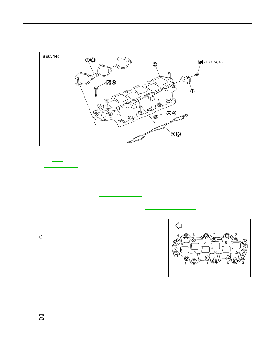
INTAKE MANIFOLD
• If stud bolts were removed, install them and tighten to the specified torque below.
1.
Harness bracket
2.
Intake manifold
3.
Gasket
A.
Refer to
Refer to
for symbols in the figure.
PBIC5453E
: Engine front
JPBIA0013ZZ
: 10.8 N·m (1.1 kg-m, 8 ft-lb)
INTAKE MANIFOLD
EM-33
< ON-VEHICLE REPAIR >
C
D
E
F
G
H
I
J
K
L
M
A
EM
N
P
O
• Tighten all mounting bolts and nuts to the specified torque in two or
more steps in numerical order as shown in the figure.
CAUTION:
Install intake manifold with the marks (put on the intake mani-
fold and the cylinder head before removal) aligned.
Inspection
INFOID:0000000003139103
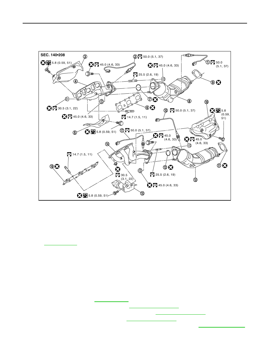
INSPECTION AFTER REMOVAL
Surface Distortion
• Check the surface distortion of the intake manifold mating surface
with a straightedge (A) and a feeler gauge (B).
• If it exceeds the limit, replace intake manifold.
: Engine front
1st step:
: 7.4 N·m (0.75 kg-m, 5 ft-lb)
2nd step and after:
: 25.5 N·m (2.6 kg-m, 19 ft-lb)
JPBIA0013ZZ
Limit
: Refer to
JPBIA0015ZZ
EM-34
< ON-VEHICLE REPAIR >
EXHAUST MANIFOLD
EXHAUST MANIFOLD
Exploded View
INFOID:0000000003139104
Removal and Installation
INFOID:0000000003139105
REMOVAL
WARNING:
Perform the work when the exhaust and cooling system have completely cooled down.
NOTE:
When removing bank 1 side parts only, step 2, 5 and 7 are unnecessary.
1.
Remove engine undercover with power tool.
2.
Drain engine coolant. Refer to
3.
Remove engine cover with power tool. Refer to
.
4.
Remove air cleaner case and air duct (RH and LH). Refer to
.
5.
Remove heater pipe and water hose. Refer to
6.
Remove exhaust front tube and three way catalysts (bank 1 and bank 2). Refer to
.
7.
Disconnect steering lower joint at power steering gear assembly side, and release steering lower shaft.
1.
Heated oxygen sensor 2 (bank 1)
2.
Air fuel ratio sensor 1 (bank 1)
3.
Exhaust manifold cover (upper)
4.
Exhaust manifold (bank 1)
5.
Exhaust manifold cover (lower)
6.
Gasket
7.
Ring gasket
8.
Three way catalyst (bank 1)
9.
Gasket
10. Heated oxygen sensor 2 (bank 2)
11. Gasket
12.
Three way catalyst (bank 2)
13. Ring gasket
14. Exhaust manifold (bank 2)
15.
Exhaust manifold cover (lower)
16. Gasket
17. Air fuel ratio sensor 1 (bank 2)
18.
Exhaust manifold cover (upper)
Refer to
for symbols in the figure.
JPBIA1909GB
Нет комментариевНе стесняйтесь поделиться с нами вашим ценным мнением.
Текст