Infiniti EX35. Manual — part 116
AV
STEERING ANGLE SENSOR SIGNAL CIRCUIT
AV-245
< COMPONENT DIAGNOSIS >
[BOSE AUDIO WITHOUT NAVIGATION]
C
D
E
F
G
H
I
J
K
L
M
B
A
O
P
STEERING ANGLE SENSOR SIGNAL CIRCUIT
Description
INFOID:0000000003544795
• Steering angle sensor signal 1, 2 detects the turning direction and quantity of the steering and transmits it to
the camera control unit.
• Steering angle sensor signal 3 detects the neutral position of the steering and transmits it to the camera con-
trol unit.
• Camera control unit performs the correction of neutral position with sensor signal 1, 2, 3 and vehicle speed
signal.
Diagnosis Procedure
INFOID:0000000003544796
1.
CHECK CONTINUITY STEERING ANGLE SENSOR SIGNAL CIRCUIT
1.
Turn ignition switch OFF.
2.
Disconnect camera control unit connector and steering angle sensor connector.
3.
Check continuity between camera control unit harness connector and steering angle sensor harness con-
nector.
4.
Check continuity between camera control unit harness connector and ground.
Is inspection result normal?
YES
>> GO TO 2.
NO
>> Repair harness or connector.
2.
CHECK VOLTAGE CAMERA CONTROL UNIT
1.
Connect camera control unit connector.
2.
Turn ignition switch ON.
3.
Check voltage between camera control unit harness connector and ground.
Is inspection result normal?
YES
>> GO TO 3.
NO
>> Replace camera control unit.
3.
CHECK STEERING ANGLE SENSOR SIGNAL
1.
Turn ignition switch OFF.
2.
Connect steering angle sensor connector.
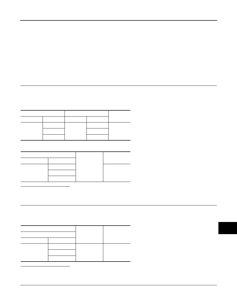
Camera control unit
Steering angle sensor
Continuity
Connector
Terminals
Connector
Terminals
B50
23
M37
3
Existed
24
4
25
5
Camera control unit
Ground
Continuity
Connector
Terminals
B50
23
Not existed
24
25
(+)
(
−
)
Reference value
(Approx.)
Camera control unit
Connector
Terminals
B50
23
Ground
5.0 V
24
25
AV-246
< COMPONENT DIAGNOSIS >
[BOSE AUDIO WITHOUT NAVIGATION]
STEERING ANGLE SENSOR SIGNAL CIRCUIT
3.
Turn ignition switch ON.
4.
Check signal between camera control unit harness connector and ground.
Is inspection result normal?
YES
>> INSPECTION END
NO
>> Replace steering angle sensor.
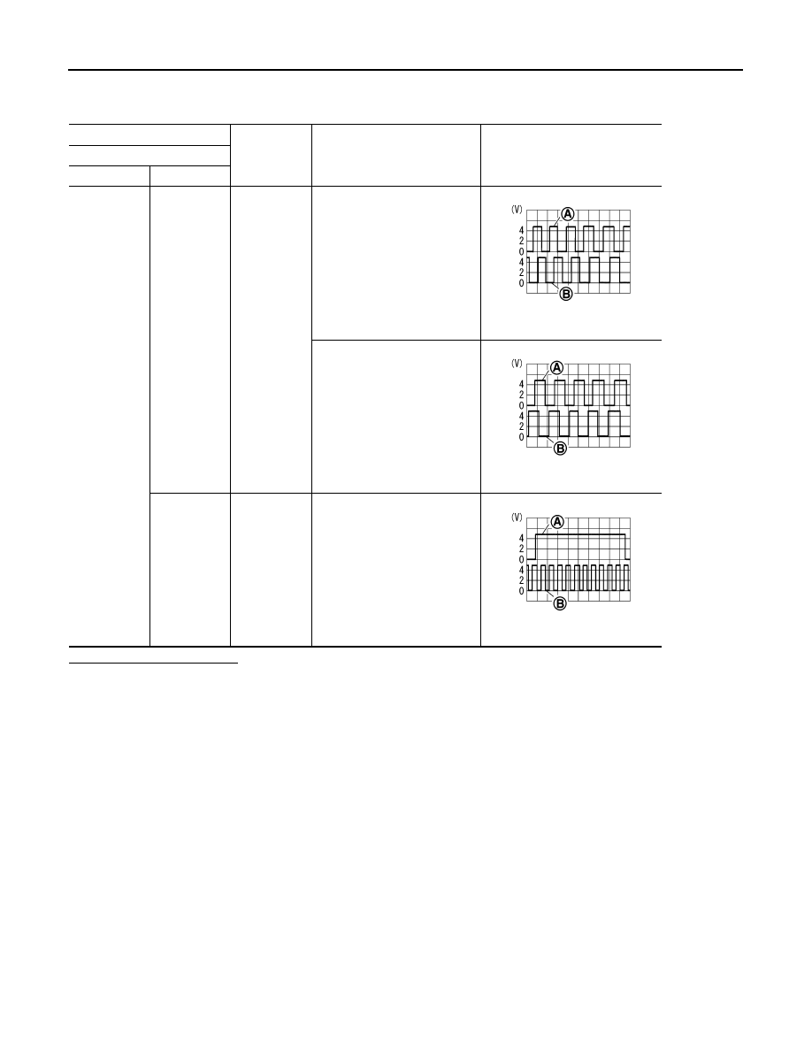
(+)
(
−
)
Condition
Reference value
Camera control unit
Connector
Terminals
B50
23, 24
Ground
Turn the steering to the right
A: Sensor signal 1
B: Sensor signal 2
Turn the steering to the left
A: Sensor signal 1
B: Sensor signal 2
25
Ground
Turn the steering around the
neutral position
A: Sensor signal 3
B: Sensor signal 1
SKIB3827E
SKIB3828E
SKIB3829E
AV
STEERING SWITCH SIGNAL A CIRCUIT
AV-247
< COMPONENT DIAGNOSIS >
[BOSE AUDIO WITHOUT NAVIGATION]
C
D
E
F
G
H
I
J
K
L
M
B
A
O
P
STEERING SWITCH SIGNAL A CIRCUIT
Description
INFOID:0000000003544797
Transmits the steering switch signal to AV control unit.
Diagnosis Procedure
INFOID:0000000003544798
1.
CHECK STEERING SWITCH SIGNAL A CIRCUIT
1.
Disconnect AV control unit connector and spiral cable connector.
2.
Check continuity between AV control unit harness connector and spiral cable harness connector.
3.
Check continuity between AV control unit harness connector and ground.
Is the inspection result normal?
YES
>> GO TO 2.
NO
>> Repair harness or connector.
2.
CHECK SPIRAL CABLE
Check spiral cable.
Is the inspection result normal?
YES
>> GO TO 3.
NO
>> Replace spiral cable.
3.
CHECK AV CONTROL UNIT VOLTAGE
1.
Connect AV control unit connector and spiral cable connector.
2.
Turn ignition switch ON.
3.
Check voltage between AV control unit harness connector.
Is the inspection result normal?
YES
>> GO TO 4.
NO
>> Replace AV control unit.
4.
CHECK STEERING SWITCH
1.
Turn ignition switch OFF.
2.
Check steering switch. Refer to
AV-248, "Component Inspection"
Is the inspection result normal?
YES
>> INSPECTION END
NO
>> Replace steering switch.
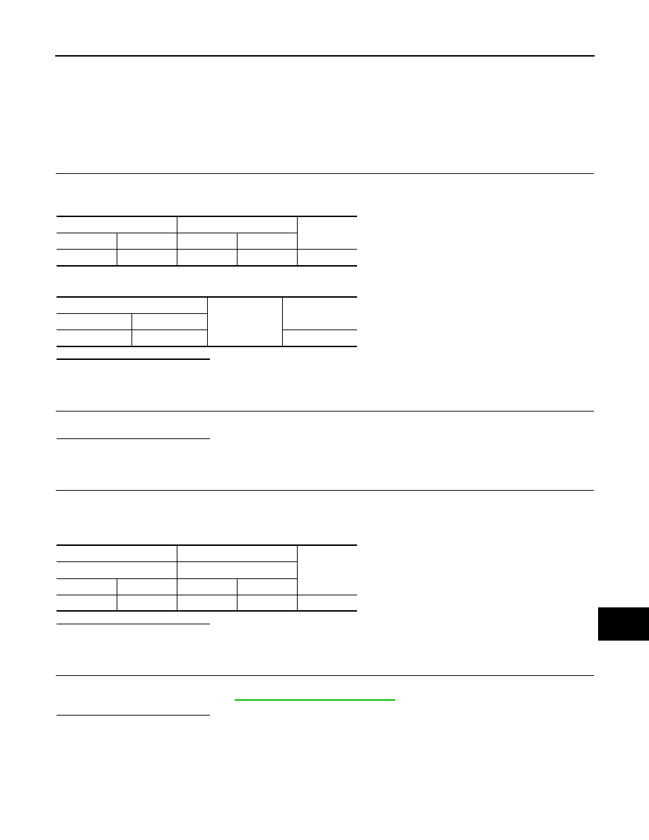
AV control unit
Spiral cable
Continuity
Connector
Terminal
Connector
Terminal
M81
6
M36
24
Existed
AV control unit
Ground
Continuity
Connector
Terminal
M81
6
Not existed
(+)
(
−
)
Reference
value
(Approx.)
AV control unit
AV control unit
Connector
Terminal
Connector
Terminal
M81
6
M81
15
3.3 V
AV-248
< COMPONENT DIAGNOSIS >
[BOSE AUDIO WITHOUT NAVIGATION]
STEERING SWITCH SIGNAL A CIRCUIT
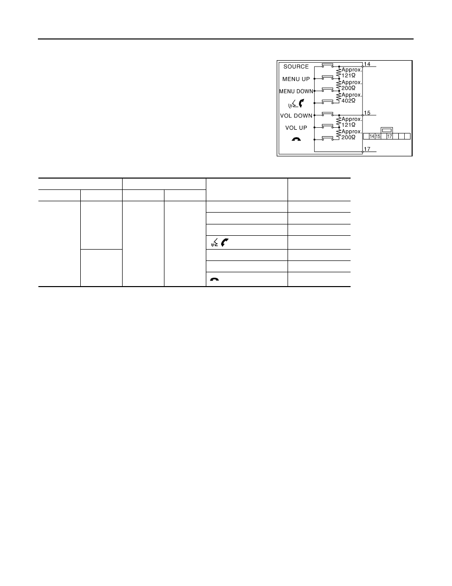
Component Inspection
INFOID:0000000003508722
Measure the resistance between the steering switch connector.
JSNIA0216GB
Steering switch
Steering switch
Condition
Resistance value
(
Ω
)
Connector
Terminal
Connector
Terminal
M303
14
M303
17
SOURCE switch ON
0
MENU UP switch ON
120 – 122
MENU DOWN switch ON
318 – 324
switch ON
716 – 730
15
VOL DOWN switch ON
0
VOL UP switch ON
120 – 122
switch ON
318 – 324
Нет комментариевНе стесняйтесь поделиться с нами вашим ценным мнением.
Текст