Infiniti EX35. Manual — part 677
EC-450
< COMPONENT DIAGNOSIS >
[VQ35HR]
FUEL INJECTOR
Is the inspection result normal?
YES
>> GO TO 3.
NO
>> GO TO 2.
2.
DETECT MALFUNCTIONING PART
Check the following.
• Harness connectors E3, F1
• IPDM E/R harness connector E7
• 10A fuse (No. 44)
• Harness for open or short between fuel injector and fuse
>> Repair open circuit or short to ground or short to power in harness or connectors.
3.
CHECK FUEL INJECTOR OUTPUT SIGNAL CIRCUIT FOR OPEN AND SHORT
1.
Turn ignition switch OFF.
2.
Disconnect ECM harness connector.
3.
Check the continuity between fuel injector harness connector and ECM harness connector.
4.
Also check harness for short to ground and short to power.
Is the inspection result normal?
YES
>> GO TO 5.
NO
>> GO TO 4
4.
DETECT MALFUNCTIONING PART
Check the following.
• Harness connectors F106, F107
• Harness for open or short between fuel injector and ECM
>> Repair open circuit or short to ground or short to power in harness or connectors.
5.
CHECK FUEL INJECTOR
EC-451, "Component Inspection"
Is the inspection result normal?
YES
>> GO TO 6.
NO
>> Replace malfunctioning fuel injector.
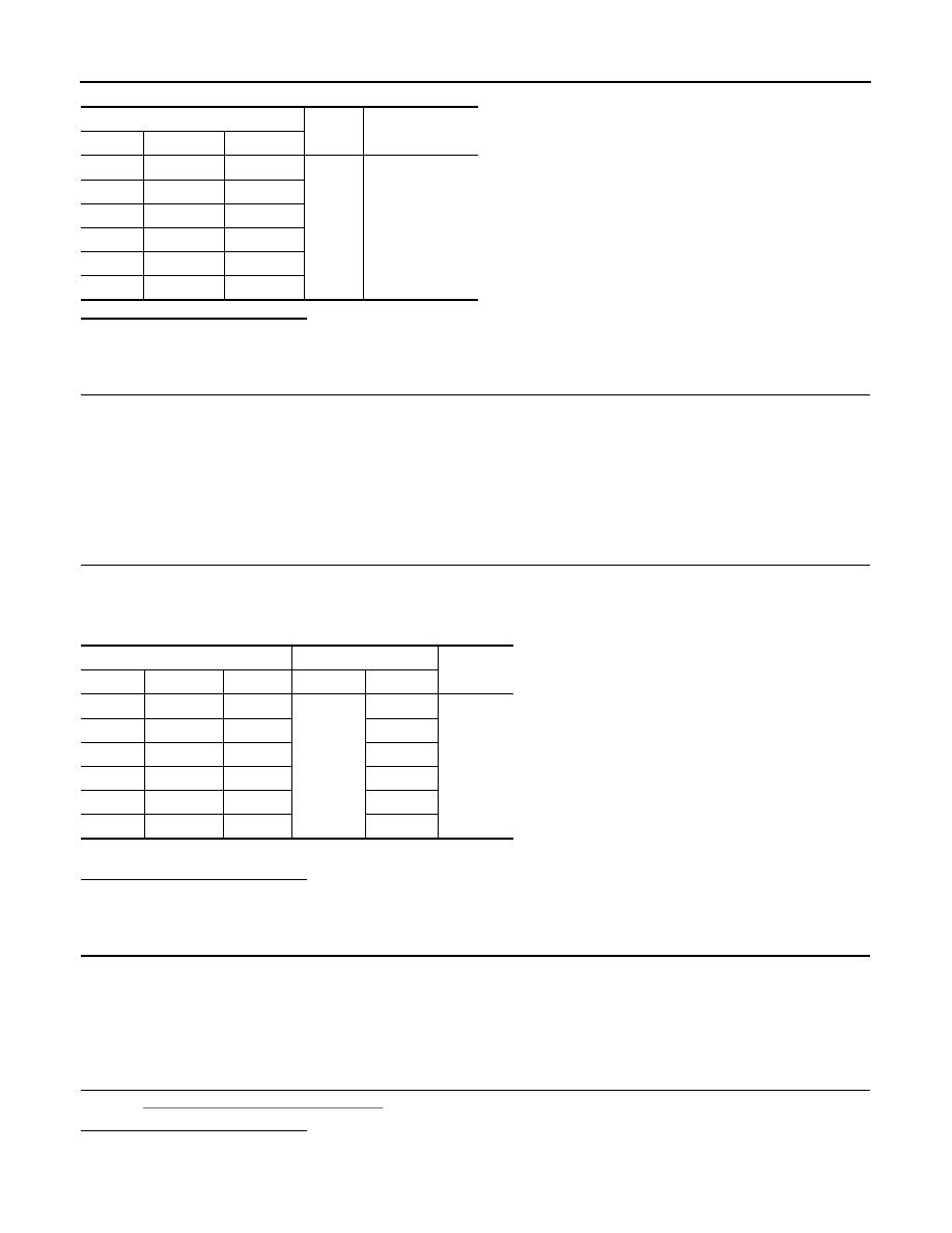
Fuel injector
Ground
Voltage
Cylinder
Connector
Terminal
1
F21
1
Ground
Battery voltage
2
F22
1
3
F23
1
4
F24
1
5
F25
1
6
F26
1
Fuel injector
ECM
Continuity
Cylinder
Connector
Terminal
Connector
Terminal
1
F21
2
F102
89
Existed
2
F22
2
85
3
F23
2
81
4
F24
2
90
5
F25
2
86
6
F26
2
82
FUEL INJECTOR
EC-451
< COMPONENT DIAGNOSIS >
[VQ35HR]
C
D
E
F
G
H
I
J
K
L
M
A
EC
N
P
O
6.
CHECK INTERMITTENT INCIDENT
GI-38, "Intermittent Incident"
.
Is the inspection result normal?
YES
>> Replace IPDM E/R.
NO
>> Repair open circuit or short to ground or short to power in harness or connectors.
Component Inspection
INFOID:0000000003133636
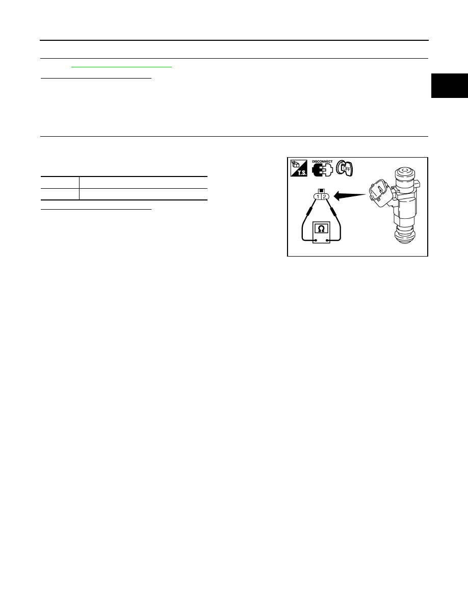
1.
CHECK FUEL INJECTOR
1.
Turn ignition switch OFF.
2.
Disconnect fuel injector harness connector.
3.
Check resistance between fuel injector terminals as follows.
Is the inspection result normal?
YES
>> INSPECTION END
NO
>> Replace malfunctioning fuel injector.
Terminals
Resistance
1 and 2
11.1 - 14.3
Ω
[at 10 - 60
°
C (60 - 140
°
F)]
PBIB1727E
EC-452
< COMPONENT DIAGNOSIS >
[VQ35HR]
FUEL PUMP
FUEL PUMP
Description
INFOID:0000000003133637
*: ECM determines the start signal status by the signals of engine speed and battery voltage.
The ECM activates the fuel pump for several seconds after the ignition switch is turned ON to improve engine
startability. If the ECM receives a engine speed signal from the camshaft position sensor (PHASE), it knows
that the engine is rotating, and causes the pump to operate. If the engine speed signal is not received when
the ignition switch is ON, the engine stalls. The ECM stops pump operation and prevents battery discharging,
thereby improving safety. The ECM does not directly drive the fuel pump. It controls the ON/OFF fuel pump
relay, which in turn controls the fuel pump.
Component Function Check
INFOID:0000000003133638
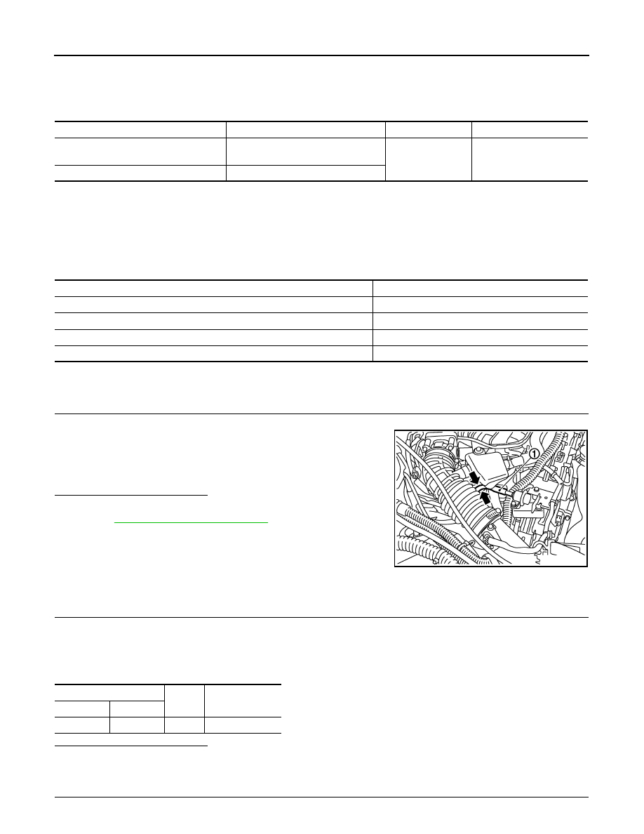
1.
CHECK FUEL PUMP FUNCTION
1.
Turn ignition switch ON.
2.
Pinch fuel feed hose (1) with two fingers.
Is the inspection result normal?
YES
>> INSPECTION END
NO
>>
.
Diagnosis Procedure
INFOID:0000000003133639
1.
CHECK FUEL PUMP POWER SUPPLY CIRCUIT-I
1.
Turn ignition switch OFF.
2.
Disconnect ECM harness connector.
3.
Turn ignition switch ON.
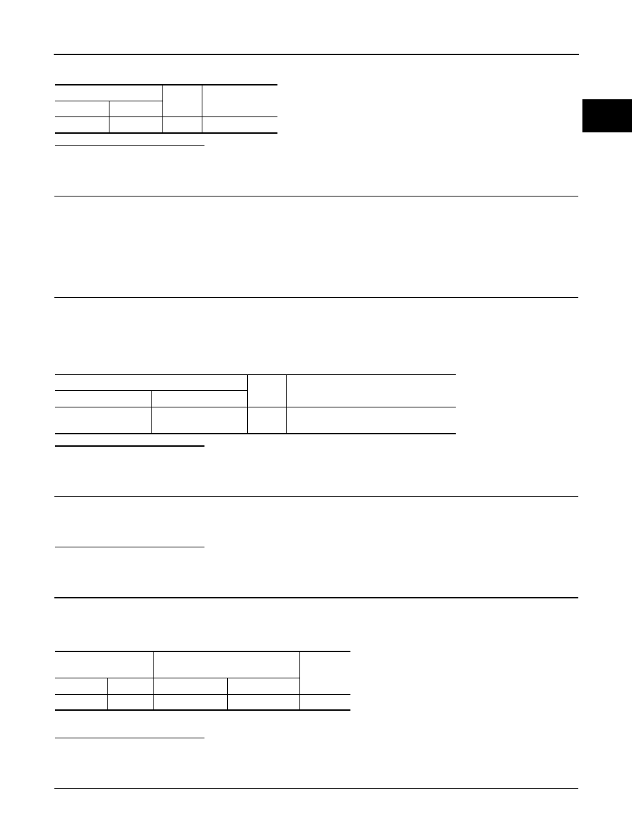
4.
Check the voltage between ECM harness connector and ground.
Is the inspection result normal?
YES
>> GO TO 4.
NO
>> GO TO 2.
2.
CHECK FUEL PUMP POWER SUPPLY CIRCUIT-II
Sensor
Input signal to ECM
ECM Function
Actuator
Crankshaft position sensor (POS)
Camshaft position sensor (PHASE)
Engine speed*
Fuel pump control
Fuel pump relay
↓
Fuel pump
Battery
Battery voltage*
Condition
Fuel pump operation
Ignition switch is turned to ON.
Operates for 1 second.
Engine running and cranking
Operates.
When engine is stopped
Stops in 1.5 seconds.
Except as shown above
Stops.
Fuel pressure pulsation should be felt on the fuel feed
hose for 1 second after ignition switch is turned ON.
JMBIA0020ZZ
ECM
Ground
Voltage
Connector
Terminal
F101
22
Ground
Battery voltage
FUEL PUMP
EC-453
< COMPONENT DIAGNOSIS >
[VQ35HR]
C
D
E
F
G
H
I
J
K
L
M
A
EC
N
P
O
Check the voltage between IPDM E/R harness connector and ground.
Is the inspection result normal?
YES
>> GO TO 3.
NO
>> GO TO 10.
3.
DETECT MALFUNCTIONING PART
Check the following.
• Harness connectors E3, F1
• Harness connectors F104, F105
• Harness for open or short between IPDM E/R and ECM
>> Repair open circuit or short to ground or short to power in harness or connectors.
4.
CHECK FUEL PUMP POWER SUPPLY CIRCUIT-III
1.
Turn ignition switch OFF.
2.
Reconnect all harness connectors disconnected.
3.
Disconnect “fuel level sensor unit and fuel pump (main)” harness connector.
4.
Turn ignition switch ON.
5.
Check the voltage between “fuel level sensor unit and fuel pump (main)” harness connector and ground.
Is the inspection result normal?
YES
>> GO TO 8.
NO
>> GO TO 5.
5.
CHECK 15A FUSE
1.
Turn ignition switch OFF.
2.
Disconnect 15A fuse (No. 41) from IPDM E/R.
3.
Check 15A fuse.
Is the inspection result normal?
YES
>> GO TO 6.
NO
>> Replace fuse.
6.
CHECK FUEL PUMP POWER SUPPLY CIRCUIT-IV
1.
Disconnect IPDM E/R harness connector E5.
2.
Check the continuity between IPDM E/R harness connector and “fuel level sensor unit and fuel pump
(main)” harness connector.
3.
Also check harness for short to ground and short to power.
Is the inspection result normal?
YES
>> GO TO 10.
NO
>> GO TO 7.
7.
DETECT MALFUNCTIONING PART
IPDM E/R
Ground
Voltage
Connector
Terminal
E7
77
Ground
Battery voltage
Fuel level sensor unit and fuel pump (main)
Ground
Voltage
Connector
Terminal
B22
1
Ground
Battery voltage should exist for 1 second
after ignition switch is turned ON.
IPDM E/R
Fuel level sensor unit and fuel pump
(main)
Continuity
Connector
Terminal
Connector
Terminal
E5
13
B22
1
Existed
Нет комментариевНе стесняйтесь поделиться с нами вашим ценным мнением.
Текст