Infiniti EX35. Manual — part 172
AV
AROUND VIEW MONITOR SYSTEM
AV-469
< FUNCTION DIAGNOSIS >
[BOSE AUDIO WITH NAVIGATION]
C
D
E
F
G
H
I
J
K
L
M
B
A
O
P
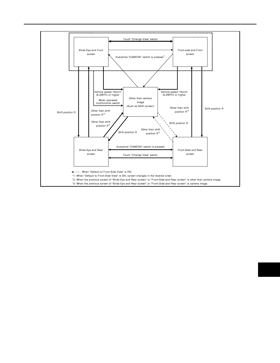
Around view monitor screen transition
FRONT VIEW
• The front view image is from the front camera.
• When the selector lever is in any position other than the reverse position, the front view is displayed by
pressing the “CAMERA” switch. It improves the visibility of obstacles in front of the vehicle and helps driving
by the images displayed from Birds-Eye view and Front-Side view.
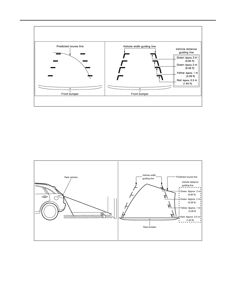
• Display the vehicle width guiding line and vehicle distance guiding line in front view and display the predicted
course line according to the steering angle.
• If the steering angle is within approximately 90 degrees, the predicted course lines on the left/right side are
displayed. If the steering angle is exceeding approximately 90 degrees, only the predicted course line on the
outside (in the opposite side of steering direction) is displayed.
• Around view monitor control unit controls the direction and distance of the predicted course line according to
the sensor signal from steering angle sensor.
JSNIA0765GB
AV-470
< FUNCTION DIAGNOSIS >
[BOSE AUDIO WITH NAVIGATION]
AROUND VIEW MONITOR SYSTEM
Front view guiding lines
REAR VIEW
• The rear view image is from the rear camera.
• When the selector lever is in the reverse position, the rear view is displayed. Backing and parking are
improved by the images from Birds-Eye view and Front-Side view.
• Display the vehicle width guiding line and vehicle distance guiding line in Rear view and display the pre-
dicted course line according to the steering angle.
• The predicted course line is not displayed at the steering neutral position. The predicted course line is dis-
played and the vehicle width guiding line is not displayed by turning the steering wheel.
• Around view monitor control unit controls the direction and distance of predicted course line according to the
sensor signal from steering angle sensor.
Rear view guiding lines
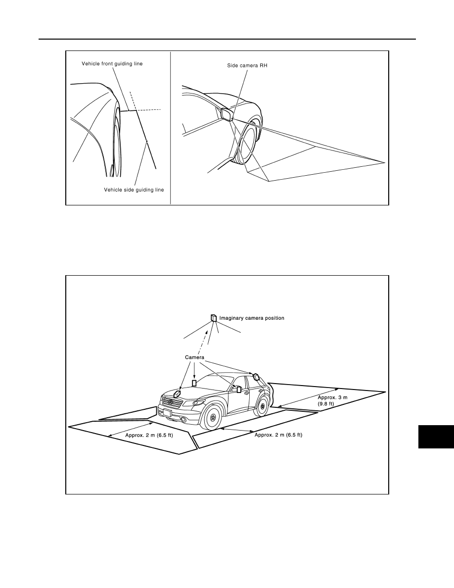
FRONT-SIDE VIEW
• The front-side view image is from the side camera RH.
• In Front-Side view, display the vehicle distance guiding line and vehicle width guiding line.
• The infrared LED illumination is installed on the door mirror RH to illuminate around the front wheels.
JSNIA0770GB
JSNIA0707GB
AV
AROUND VIEW MONITOR SYSTEM
AV-471
< FUNCTION DIAGNOSIS >
[BOSE AUDIO WITH NAVIGATION]
C
D
E
F
G
H
I
J
K
L
M
B
A
O
P
Front-side view area and guiding line
BIRDS-EYE VIEW
• The image from the 4 cameras is cut out and converted into the overhead view, and the surroundings of the
vehicle is displayed in birds-eye view.
• In Birds-Eye view, the invisible area is displayed on the image to specify the boundary of the 4 cameras.
• The invisible area is displayed in yellow in the Birds-Eye view after turning the ignition switch ON as an infor-
mation for the user. (OFF setting can be performed)
Birds-Eye view display image
JSNIA0771GB
JSNIA0767GB

AV-472
< FUNCTION DIAGNOSIS >
[BOSE AUDIO WITH NAVIGATION]
AROUND VIEW MONITOR SYSTEM
Birds-Eye view display area
CAMERA IMAGE OPERATION PRINCIPLE
• If the information writing to around view monitor control unit and the information from the camera are not
matched, the applicable camera position is indicated as an error on the Birds-Eye view display. (Calibration
operation is necessary when replacing each camera or when replacing around view monitor control unit.)
• Around view monitor control unit receives the camera switch signal from AV control unit via AV communica-
tion by pressing the “CAMERA” switch of multifunction switch.
• Around view monitor control unit that receives the camera switch signal supplies the power to each camera
and inputs the camera image from each camera.
• When the selector lever is in the reverse position, around view monitor control unit receives the reverse sig-
nal from AV control unit via AV communication, supplies the power to each camera, and inputs the camera
image from each camera.
• Around view monitor control unit that receives the camera image signal from each camera cuts out the
required screen for each view, superimposes the camera image, vehicle icon, guiding lines, sonar indicator,
and outputs them to the display unit.
PREDICTED COURSE LINE OPERATION PRINCIPLE
Detection of steering rotation direction
Around view monitor control unit detects the rotation direction of steering according to the phase difference of
two pairs of pulse signals (sensor signal 1 and sensor signal 2) input from steering angle sensor.
Detection of steering neutral position
The sensor signal 3 input from the steering angle sensor is generated at 1 pulse per 1 rotation of the steering
wheel. Around view monitor control unit detects the steering neutral position from this pulse.
JSNIA0775GB
Нет комментариевНе стесняйтесь поделиться с нами вашим ценным мнением.
Текст