Infiniti EX35. Manual — part 104
AV
DIAGNOSIS SYSTEM (AV CONTROL UNIT)
AV-197
< FUNCTION DIAGNOSIS >
[BOSE AUDIO WITHOUT NAVIGATION]
C
D
E
F
G
H
I
J
K
L
M
B
A
O
P
The tint of the color bar indication is as per the following list if a RGB signal error is detected.
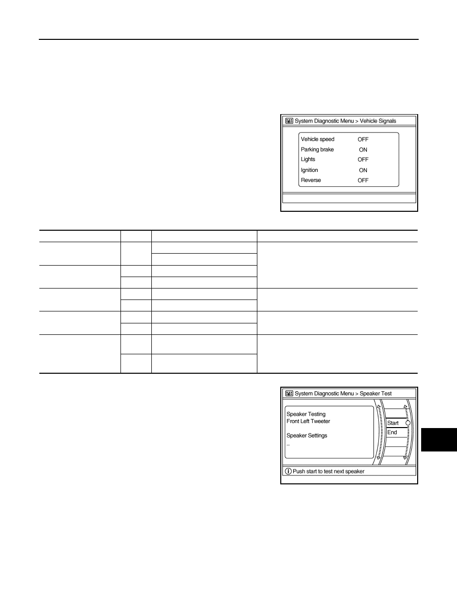
Vehicle Signals
A comparison check can be made of each actual vehicle signal and
the signals recognized by the system.
Speaker Test
Select “SPEAKER DIAGNOSIS” to display the Speaker Diagnosis
screen. Press “START and NEXT” to generate a test tone in a
speaker. Press “Start” to generate a test tone in the next speaker.
Press “End” to stop the test tones.
NOTE:
The frequency of test tone emitted from each speaker is as follows.
*: Squawker
Climate Control
Refer to “HEATER & AIR CONDITIONING CONTROL SYSTEM” for details.
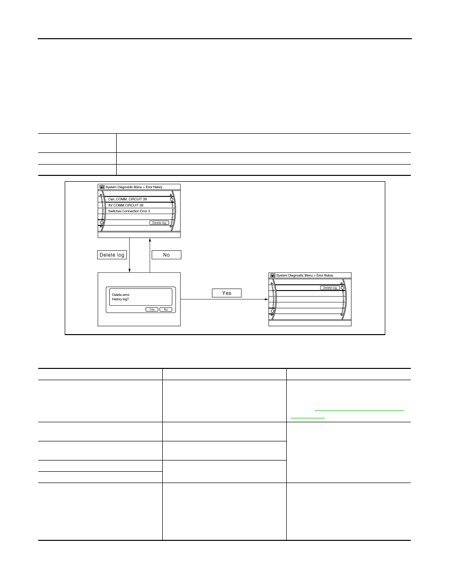
Error History
The self-diagnosis results are judged depending on whether any error occurs from when “Self-diagnosis” is
selected until the self-diagnosis results are displayed.
However, the diagnosis results are judged normal if an error has occurred before the ignition switch is turned
ON and then no error has occurred until the self-diagnosis start. Check the “Error Record” to detect any error
that may have occurred before the self-diagnosis start because of this condition.
R (red) signal error
: Light blue (Cyan) tint
G (green) signal error
: Purple (Magenta) tint
B (blue) signal error
: Yellow tint
JSNIA0149GB
Diagnosis item
Display
Vehicle status
Remarks
Vehicle speed
ON
Vehicle speed > 0 km/h (0 MPH)
Changes in indication may be delayed. This is normal.
Vehicle speed = 0 km/h (0 MPH)
Parking brake
ON
Parking brake is applied.
OFF
Parking brake is released.
Lights
ON
Light switch ON
—
OFF
Light switch OFF
Ignition
ON
Ignition switch ON
—
OFF
Ignition switch ACC
Reverse
ON
Shift the selector lever to the “R” po-
sition
Changes in indication may be delayed. This is normal.
OFF
Shift the selector lever to a position
other than the “R” position
Tweeter*
: 3 kHz
Front speaker
: 300 Hz
Rear speaker
: 1 kHz
JSNIA0150GB
AV-198
< FUNCTION DIAGNOSIS >
[BOSE AUDIO WITHOUT NAVIGATION]
DIAGNOSIS SYSTEM (AV CONTROL UNIT)
Count up method A
• The counter resets to 0 if an error occurs when the ignition switch is turned ON. The counter increases by 1
if the condition is normal at the next IGN ON cycle.
• The counter upper limit is 39. Any counts exceeding 39 are ignored. The counter can be reset (no error
record display) with the “Delete log” switch or CONSULT-III.
Count up method B
• The counter increases by 1 if an error occurs when the ignition switch is ON. The counter will not decrease
even if the condition is normal at the next IGN ON cycle.
• The counter upper limit is 50. Any counts exceeding 50 are ignored. The counter can be reset (no error
record display) with the “Delete log” switch or CONSULT-III.
Error item
Error items may be displayed simultaneously according to the cause. If error items are displayed simulta-
neously, the cause can be detected by the combination of display items.
Display type of occur-
rence frequency
Error history display item
Count up method A
CAN communication line, control unit (CAN), AV communication line, control unit (AV communication)
Count up method B
Other than the above
JSNIA0151GB
Error item
Description
Possible malfunction factor/Action to take
CAN COMM CIRCUIT
CAN communication malfunction is detect-
ed.
Perform diagnosis with CONSULT-III, and
then repair malfunctioning parts according
to the diagnosis results.
Refer to
CONTROL UNIT (CAN)
CAN initial diagnosis malfunction is detect-
ed.
Replace AV control unit.
CONTROL UNIT (AV)
AV communication circuit initial diagnosis
malfunction is detected.
FLASH-ROM Error Of Control Unit
AV control unit malfunction is detected.
CAN Controller Memory Error
Front Display Connection Error
When either one of the following items
are detected:
• Display unit power supply or ground cir-
cuits malfunction are detected.
• Malfunction is detected in the communi-
cation circuits between AV control unit
and display unit.
• Display unit power supply and ground
circuits.
• Communication circuits between AV con-
trol unit and display unit.

AV
DIAGNOSIS SYSTEM (AV CONTROL UNIT)
AV-199
< FUNCTION DIAGNOSIS >
[BOSE AUDIO WITHOUT NAVIGATION]
C
D
E
F
G
H
I
J
K
L
M
B
A
O
P
SAT Connection Error
When either one of the following items
are detected:
• Satellite radio tuner power supply or
ground circuits malfunction are detected.
• Malfunction is detected in the communi-
cation circuits between AV control unit
and satellite radio tuner.
• Malfunction is detected in the request
signal circuit between AV control unit and
satellite radio tuner.
• Satellite radio tuner power supply and
ground circuits.
• Communication circuits between AV con-
trol unit and satellite radio tuner.
• Request signal circuit between AV con-
trol unit and satellite radio tuner.
Camera Control Unit Connection Error
Malfunction is detected in the camera con-
nection recognition circuit between AV con-
trol unit and camera control unit.
Camera-connection recognition circuit be-
tween AV control unit and camera control
unit.
• AV COMM CIRCUIT
• Switches Connection Error
When either one of the following items
are detected:
• Multifunction switch power supply or
ground circuits malfunction are detected.
• Malfunction is detected in the AV com-
munication circuits between AV control
unit and the junction between AV control
unit and multifunction switch.
• Multifunction switch power supply and
ground circuits.
• AV communication circuits between AV
control unit and the junction between AV
control unit and multifunction switch.
• AV COMM CIRCUIT
• iPod Connection Error
When either one of the following items
are detected:
• iPod adapter unit power supply or ground
circuits malfunction are detected.
• Malfunction is detected in the AV com-
munication circuits between AV control
unit and the junction between AV control
unit and iPod adapter.
• iPod adapter power supply and ground
circuits.
• AV communication circuits between AV
control unit and the junction between AV
control unit and iPod adapter.
• AV COMM CIRCUIT
• Rear View Camera Connection Error
Camera control unit power supply or
ground circuits malfunction is detected.
Camera control unit power supply and
ground circuits.
• AV COMM CIRCUIT
• H/F Unit Connection Error
WITHOUT REAR VIEW MONITOR
When either one of the following items
are detected:
• TEL adapter unit power supply or ground
circuits malfunction are detected.
• Malfunction is detected in the AV com-
munication circuits between TEL adapter
unit and the junction between AV control
unit and multifunction switch.
• TEL adapter unit power supply and
ground circuits.
• AV communication circuits between TEL
adapter unit and the junction between AV
control unit and multifunction switch.
WITH REAR VIEW MONITOR
When either one of the following items
are detected:
• TEL adapter unit power supply or ground
circuits malfunction are detected.
• Malfunction is detected in the AV com-
munication circuits between camera con-
trol unit and TEL adapter unit.
• TEL adapter unit power supply and
ground circuit.
• AV communication circuits between cam-
era control unit and TEL adapter unit.
• AV COMM CIRCUIT
• Rear View Camera Connection Error
• H/F Unit Connection Error
Malfunction is detected in the AV communi-
cation circuits between camera control unit
and the junction between camera control
unit and multifunction switch.
AV communication circuits between cam-
era control unit and the junction between
camera control unit and multifunction
switch.
• AV COMM CIRCUIT
• Switches Connection Error
• iPod Unit Connection Error
• H/F Unit Connection Error
Malfunction is detected in the AV communi-
cation circuits between the AV control unit
and the junction between AV control unit
and multifunction switch.
AV communication circuits between AV
control unit and the junction between AV
control unit and multifunction switch.
• AV COMM CIRCUIT
• Switches Connection Error
• iPod Unit Connection Error
• Rear View Camera Connection Error
• H/F Unit Connection Error
Malfunction is detected in the AV communi-
cation circuits between AV control unit and
the junction between AV control unit and
multifunction switch.
AV communication circuits between AV
control unit and the junction between AV
control unit and multifunction switch.
Error item
Description
Possible malfunction factor/Action to take
AV-200
< FUNCTION DIAGNOSIS >
[BOSE AUDIO WITHOUT NAVIGATION]
DIAGNOSIS SYSTEM (AV CONTROL UNIT)
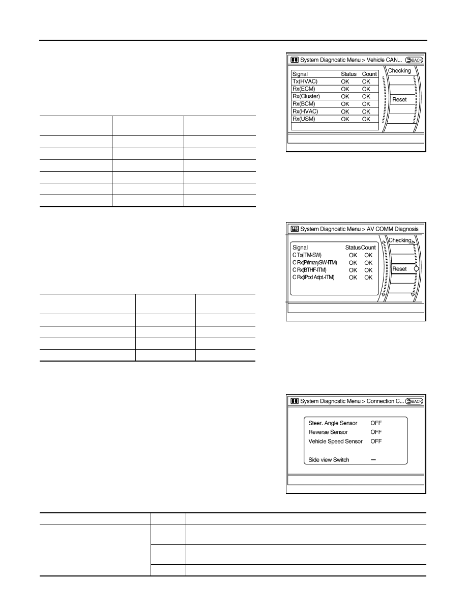
Vehicle CAN Diagnosis
• CAN communication status and error counter is displayed.
• The error counter displays “OK” if a malfunction was not detected
in the past and displays “0” if a malfunction is detected. It increases
by 1 if the condition is normal at the next ignition switch ON cycle.
The upper limit of the counter is 39.
• The error counter is erased if reset.
AV COMM Diagnosis
• Displays the communication status between AV control unit (mas-
ter unit) and each unit.
• The error counter displays “OK” if any malfunction was not
detected in the past and displays “0” if a malfunction is detected. It
increases by 1 if the condition is normal at the next ignition switch
ON cycle. The upper limit of the counter is 39.
• The error counter is erased if reset.
Camera Cont.
The two functions of “Connection Confirmation” and “Adjust Offset of Rear View Camera” are available.
CONNECTION CONFIRMATION
The steering angle sensor, reverse signal and vehicle speed sensor
can be inspected.
Items
Display (Current)
Malfunction counter
(Past)
Tx(HVAC)
OK / UNKWN
OK / 0 - 39
Rx(ECM)
OK / UNKWN
OK / 0 - 39
Rx(Cluster)
OK / UNKWN
OK / 0 - 39
Rx(BCM)
OK / UNKWN
OK / 0 - 39
Rx(HVAC)
OK / UNKWN
OK / 0 - 39
Rx(USM)
OK / UNKWN
OK / 0 - 39
JSNIA0080GB
Items
Status
(Current)
Counter
(Past)
C Tx(ITM–SW)
OK / UNKWN
OK / 0 - 39
C Rx(PrimarySW–ITM)
OK / UNKWN
OK / 0 - 39
C Rx(BTHF–ITM)
OK / UNKWN
OK / 0 - 39
C Rx(iPod Adpt.–ITM)
OK / UNKWN
OK / 0 - 39
JPNIA0512GB
JSNIA0084GB
Diagnosis item
Display
Vehicle status
Steer. Angle Sensor
ON
When steering the vehicle with ignition switch ON (remains ON until connection
mode is stopped when it is turned ON)
OFF
• Ignition switch at ACC
• No steering with ignition switch ON
—
Malfunction detected in camera connection recognition signal
Нет комментариевНе стесняйтесь поделиться с нами вашим ценным мнением.
Текст