Infiniti EX35. Manual — part 102
AV
REAR VIEW MONITOR SYSTEM
AV-189
< FUNCTION DIAGNOSIS >
[BOSE AUDIO WITHOUT NAVIGATION]
C
D
E
F
G
H
I
J
K
L
M
B
A
O
P
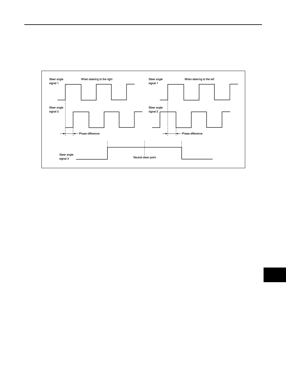
PREDICTED COURSE LINE OPERATION PRINCIPLE
Detection of steering rotation direction
Camera control unit detects the rotation direction of steering according to the phase difference of two pairs of
pulse signals (sensor signal 1 and sensor signal 2) input from steering angle sensor.
Detection of steering neutral position
The sensor signal 3 input from steering angle sensor is generated at 1 pulse per 1 rotation of the steering
wheel. Camera control unit detects the steering neutral position from this pulse.
Correction of steering neutral position
Camera control unit corrects the steering neutral position during driving according to the vehicle speed signal
and sensor signal.
JSNIA0708GB
AV-190
< FUNCTION DIAGNOSIS >
[BOSE AUDIO WITHOUT NAVIGATION]
REAR VIEW MONITOR SYSTEM
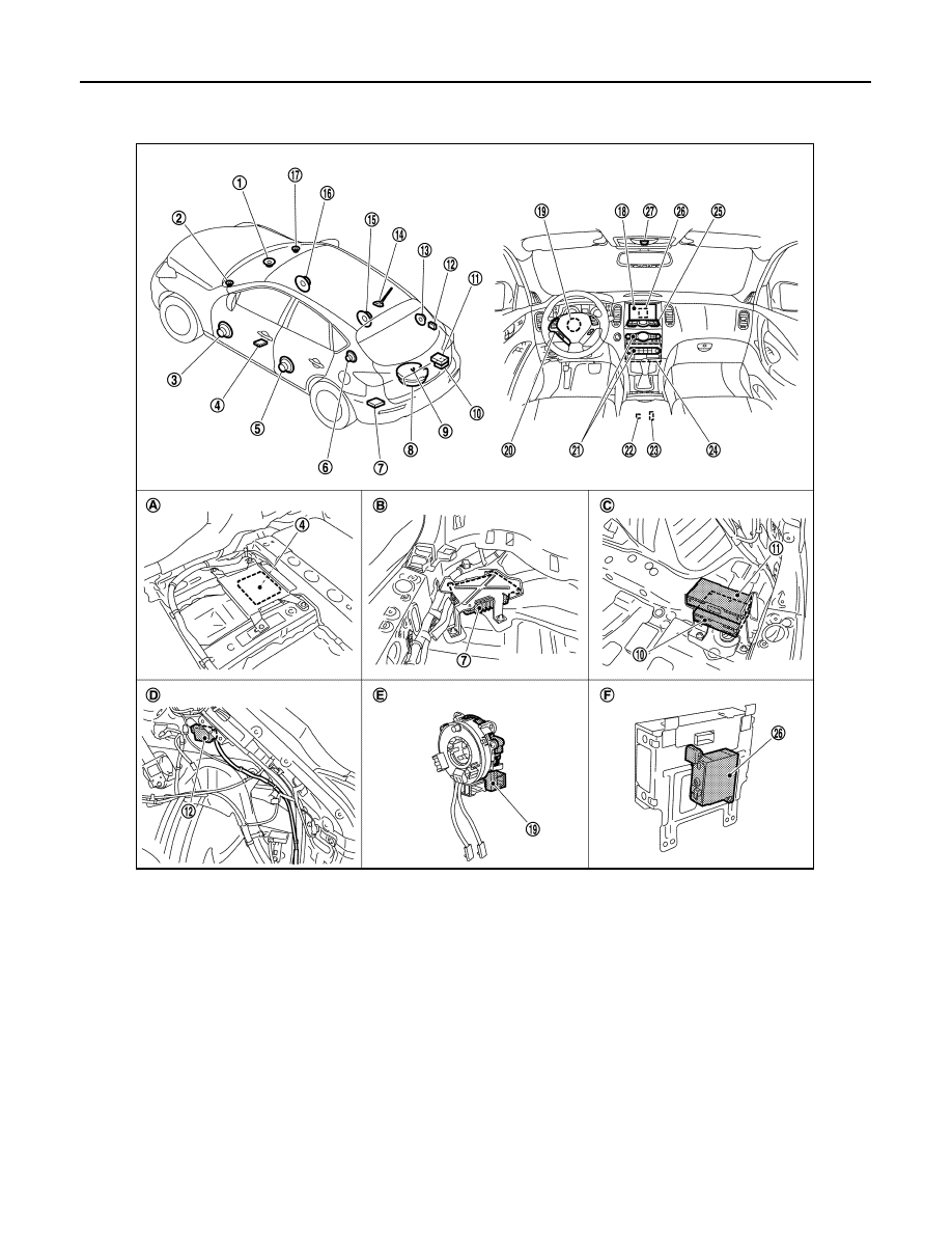
Component Parts Location
INFOID:0000000003579815
1.
Center speaker
2.
Front squawker LH
3.
Front door speaker LH
4.
Camera control unit
5.
Rear door speaker LH
6.
Rear squawker LH
7.
BOSE amp.
8.
Woofer
9.
Rear view camera
10. Satellite radio tuner
11. TEL adapter unit
12. TEL antenna
13. Rear squawker RH
14. Antenna base (antenna amp and sat-
ellite antenna)
15. Rear door speaker RH
16. Front door speaker RH
17. Front squawker RH
18. Display unit
19. Steering angle sensor
20. Steering switch
21. Preset switch
22. iPod connector
23. Auxiliary input jacks
24. AV control unit
25. Multifunction switch
26. iPod adapter
27. Microphone
A.
Under front seat (LH side)
B.
Luggage floor (LH side)
C.
Luggage floor (RH side)
D.
Luggage side RH
E.
Spiral cable part
F.
Rear view of the display unit
JPNIA0910ZZ

AV
REAR VIEW MONITOR SYSTEM
AV-191
< FUNCTION DIAGNOSIS >
[BOSE AUDIO WITHOUT NAVIGATION]
C
D
E
F
G
H
I
J
K
L
M
B
A
O
P
Component Description
INFOID:0000000003534102
Part name
Description
AV CONTROL UNIT
• Image on display is transmitted to rear view monitor image by serial communi-
cation between AV control unit and display unit.
• Warning displayed on the rear view monitor image is illustrated.
• AV control unit recognizes the presence of camera system with camera con-
nection recognition signal.
DISPLAY UNIT
• Camera image signal is input from AV control unit.
• RGB signal for warning display is input from AV control unit.
• Rear view monitor image is changed by serial communication from AV control
unit.
CAMERA CONTROL UNIT
• Camera image signal is input from rear view camera. Camera image signal is
output to AV control unit.
• Power (camera ON signal) is transmitted to rear view camera.
• Superimpose the guiding line and predicted course line to the camera image
that outputs to AV control unit.
• Inputs the sensor signal from steering angle sensor, and then controls the pre-
dicted course line.
• Camera control unit is connected via AV communication.
REAR VIEW CAMERA
• The image of vehicle rear view is transmitted to camera control unit.
• It receives power (camera ON signal) from camera control unit and operates.
STEERING ANGLE SENSOR
Steering signal necessary for predicted course line control is transmitted to cam-
era control unit.
AV-192
< FUNCTION DIAGNOSIS >
[BOSE AUDIO WITHOUT NAVIGATION]
DIAGNOSIS SYSTEM (AV CONTROL UNIT)
DIAGNOSIS SYSTEM (AV CONTROL UNIT)
Diagnosis Description
INFOID:0000000003508662
MULTIFUNCTION SWITCH AND PRESET SWITCH SELF-DIAGNOSIS FUNCTION
The ON/OFF operation (continuity) of each switch in the multifunction switch and preset switch can be
checked.
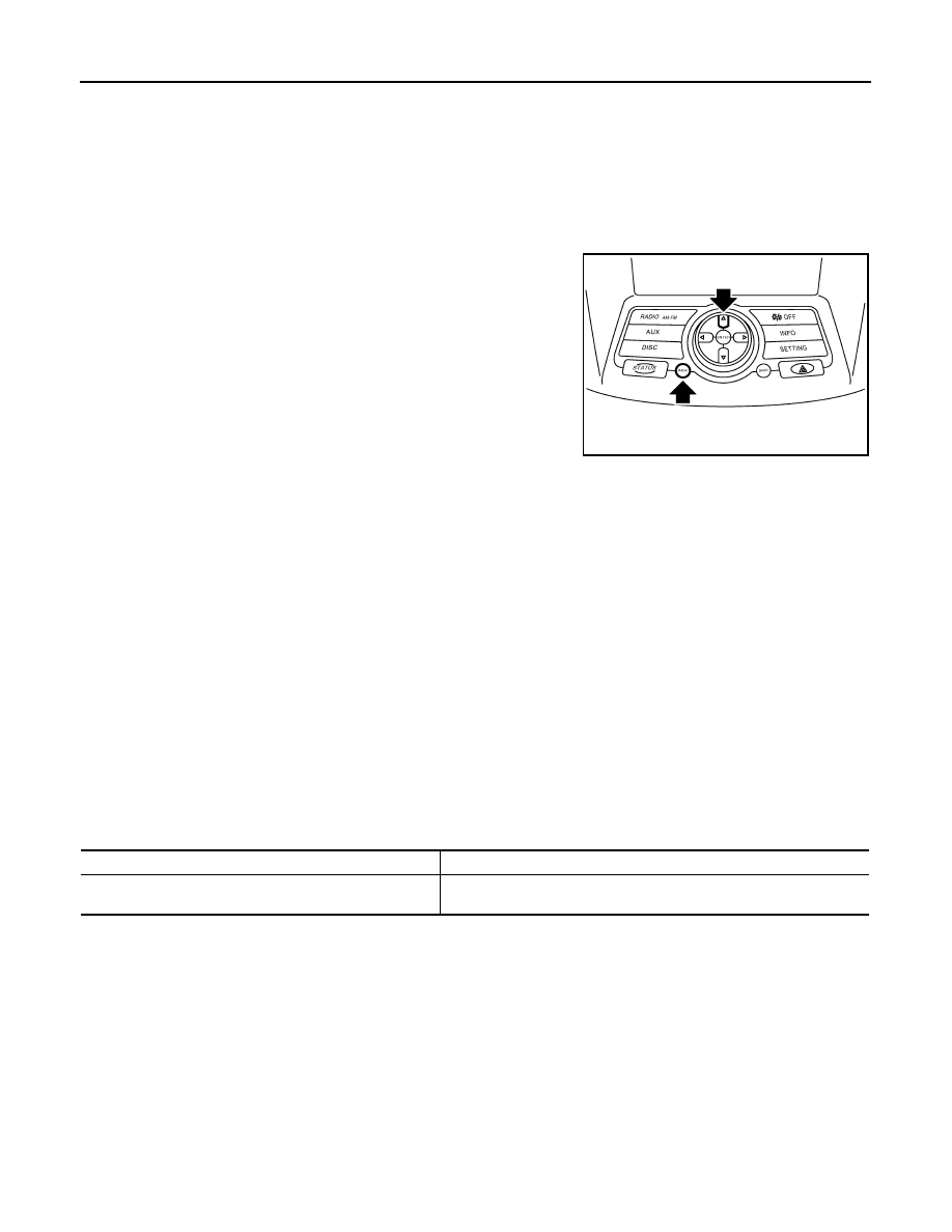
Self-diagnosis mode
• Press the “BACK” switch and the “UP” switch of the 4-direction
switches within 10 seconds after turning the ignition switch from
OFF to ACC and hold them for 3 seconds or more. The buzzer
sounds, all indicators of the preset switch illuminate, and the self-
diagnosis mode starts.
• The continuity of each switch in the ON position can be checked by
pressing the switch. The buzzer sounds if the switch is normal.
CAUTION:
The hazard switch and disk eject switch cannot be checked.
Finishing self-diagnosis mode
Self-diagnosis mode is canceled when turning the ignition switch OFF.
MULTI AV SYSTEM ON BOARD DIAGNOSIS FUNCTION
• The AV control unit diagnosis function starts up with multifunction switch operation and AV control unit per-
forms a diagnosis for each unit in the system during the on board diagnosis.
• Perform a CONSULT-III diagnosis if the on board diagnosis does not start, e.g., the screen does not display
anything, multifunction switch does not function, etc.
ON BOARD DIAGNOSIS
Description
• The trouble diagnosis function has a self-diagnosis mode for conducting trouble diagnosis automatically and
a confirmation/adjustment mode for operating manually.
• Self-diagnosis mode performs AV control unit diagnosis and the connection diagnosis between each of the
units that make up the system, and it indicates the results to the display.
• The confirmation/adjustment mode allows the technician to check, modify or adjust the vehicle signals and
set values, as well as to monitor the system error records and system communication status. The checking,
modifying or adjusting generally requires human intervention and judgment (the system cannot make judg-
ment automatically).
On board diagnosis item
JSNIA0136GB
Mode
Description
Self Diagnosis
• AV control unit diagnosis
• Perform the connection diagnosis between each of the units.
Нет комментариевНе стесняйтесь поделиться с нами вашим ценным мнением.
Текст