Infiniti EX35. Manual — part 105
AV
DIAGNOSIS SYSTEM (AV CONTROL UNIT)
AV-201
< FUNCTION DIAGNOSIS >
[BOSE AUDIO WITHOUT NAVIGATION]
C
D
E
F
G
H
I
J
K
L
M
B
A
O
P
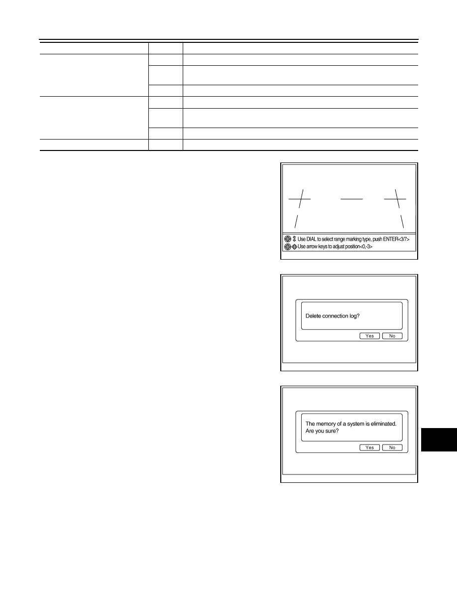
ADJUST OFFSET OF REAR VIEW CAMERA
Use this mode to adjust the guide line display position of the rear
view monitor if necessary after removing the rear view monitor cam-
era.
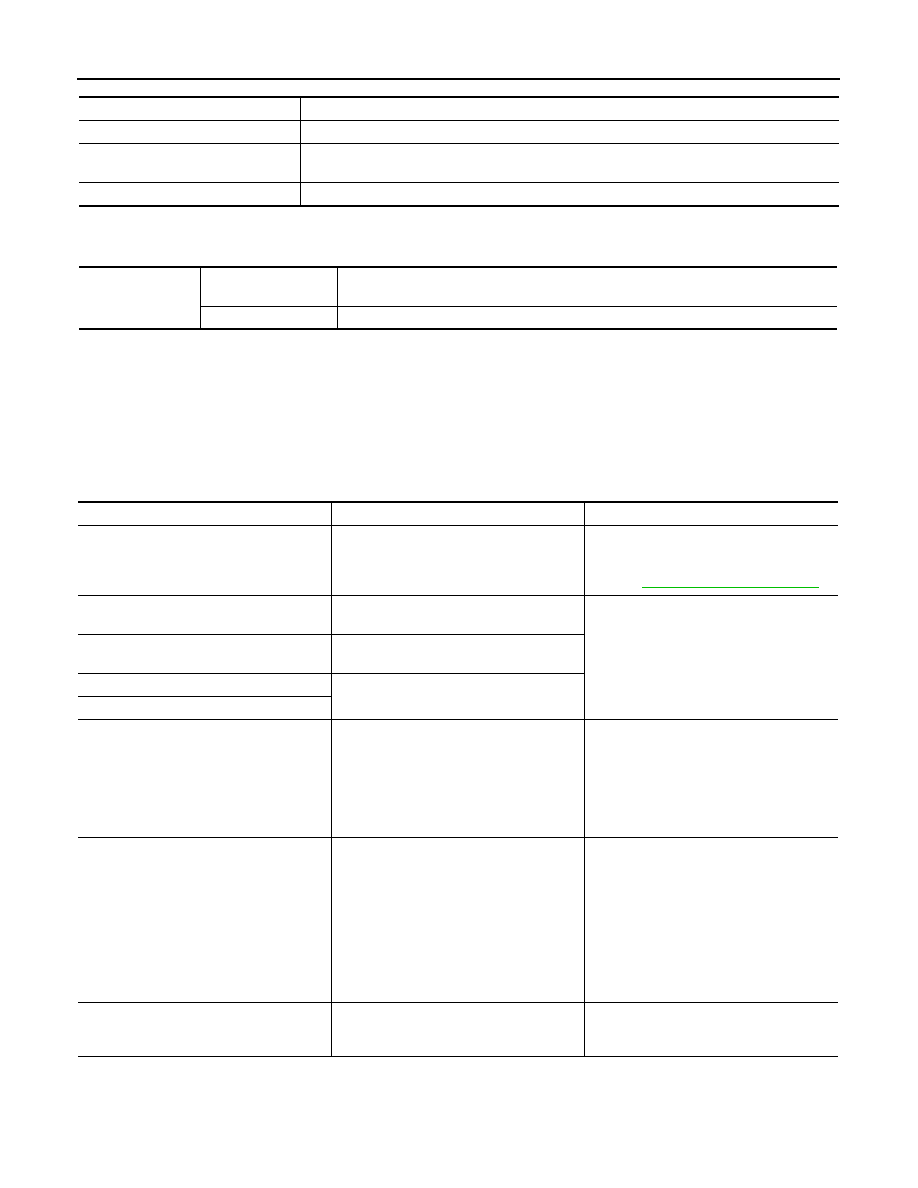
Delete Unit Connection Log
Deletes any unit connection records and error records from AV con-
trol unit memory. (Clear the records of the unit that has been
removed.)
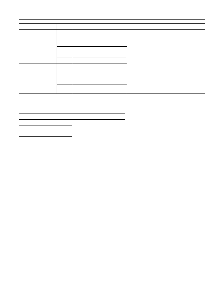
Initialize Settings
Initializes AV control unit memory.
CONSULT-III Function (MULTI AV)
INFOID:0000000003508663
CONSULT-III functions
CONSULT-III performs the following functions via the communication with AV control unit.
Reverse Sensor
ON
Selector lever is in “R” with ignition switch ON
OFF
• Ignition switch at ACC
• Selector lever is in position other than “R” with ignition switch ON
—
Malfunction detected in camera-connection recognition signal
Vehicle Speed Sensor
ON
Vehicle speed is more than 0 km/h (0 MPH) with ignition switch ON
OFF
• Ignition switch at ACC
• Vehicle speed is 0 km/h (0 MPH) with ignition switch ON
—
Malfunction detected in camera connection recognition signal
Side view Switch
—
Not used
Diagnosis item
Display
Vehicle status
JSNIA0085GB
JSNIA0154GB
JSNIA0155GB
AV-202
< FUNCTION DIAGNOSIS >
[BOSE AUDIO WITHOUT NAVIGATION]
DIAGNOSIS SYSTEM (AV CONTROL UNIT)
AV COMMUNICATION
When “AV communication” of “CAN Diag Support Monitor” is selected, the following function will be performed.
ECU IDENTIFICATION
The part number of AV control unit is displayed.
SELF DIAGNOSIS RESULT
• In CONSULT-III self-diagnosis, self-diagnosis results and error history are displayed simultaneously.
• The timing is displayed as “0” if any of the error codes [U1000], [U1010], [U1300] or [U1310] are detected.
The counter increases by 1 if the condition is normal at the next ignition switch ON cycle.
Self-diagnosis results display item
Diagnosis mode
Description
Ecu Identification
The part number of AV control unit can be checked.
Self Diagnostic Result
Performs a diagnosis on AV control unit, a connection diagnosis for the communication circuit
of the Multi AV system and displays the current and past malfunctions collectively.
Data Monitor
The diagnosis of vehicle signal that is input to AV control unit can be performed.
AV communication
AV&NAVI C/U
Displays the communication status from AV control unit to each unit as well as the error
counter.
AUDIO
Displays AV control unit communication status and the error counter.
Error item
Description
Possible malfunction factor/Action to take
CAN COMM CIRCUIT [U1000]
CAN communication malfunction is detect-
ed.
Perform diagnosis with CONSULT-III, and
then repair the malfunctioning parts accord-
ing to the diagnosis results.
Refer to
.
CONTROL UNIT (CAN) [U1010]
CAN initial diagnosis malfunction is detect-
ed.
Replace AV control unit.
CONTROL UNIT (AV) [U1310]
AV communication circuit initial diagnosis
malfunction is detected.
Control Unit FLASH-ROM [U1200]
AV control unit malfunction is detected.
CAN CONT [U1216]
FRONT DISP CONN [U1243]
When either one of the following items
are detected:
• Display unit power supply or ground cir-
cuits malfunction are detected.
• Malfunction is detected in communica-
tion circuits between AV control unit and
display unit.
• Display unit power supply and ground
circuits.
• Communication circuits between AV con-
trol unit and display unit.
SAT CONN [U1255]
When either one of the following items
are detected:
• Satellite radio tuner power supply or
ground circuits malfunction are detected.
• Malfunction is detected in communica-
tion circuits between AV control unit and
satellite radio tuner.
• Malfunction is detected in request signal
circuits between AV control unit and sat-
ellite radio tuner.
• Satellite radio tuner power supply and
ground circuits.
• Communication circuits between AV con-
trol unit and satellite radio tuner.
• Request signal circuits between AV con-
trol unit and satellite radio tuner.
CAMERA CONT. CONN [U1250]
Malfunction is detected in camera connec-
tion recognition circuit between AV control
unit and camera control unit.
Camera-connection recognition circuit be-
tween AV control unit and camera control
unit.

AV
DIAGNOSIS SYSTEM (AV CONTROL UNIT)
AV-203
< FUNCTION DIAGNOSIS >
[BOSE AUDIO WITHOUT NAVIGATION]
C
D
E
F
G
H
I
J
K
L
M
B
A
O
P
DATA MONITOR
ALL SIGNALS
• Displays the status of the following vehicle signals inputted into AV control unit.
• For each signal, actual signal can be compared with the condition recognized on the system.
• AV COMM CIRCUIT [U1300]
• SWITCH CONN [U1240]
When either one of the following items
are detected:
• Multifunction switch power supply or
ground circuits malfunction are detected.
• Malfunction is detected in AV communi-
cation circuits between AV control unit
and the junction between AV control unit
and multifunction switch.
• Multifunction switch power supply and
ground circuits.
• AV communication circuits between AV
control unit and the junction between AV
control unit and multifunction switch.
• AV COMM CIRCUIT [U1300]
• IPod CONN [U1254]
When either one of the following items
are detected:
• iPod adapter power supply or ground cir-
cuits malfunction are detected.
• Malfunction is detected in AV control unit
and the junction between AV control unit
and iPod adapter.
• iPod adapter power supply and ground
circuits.
• AV communication circuits between AV
control unit and the junction between AV
control unit and iPod adapter.
WITH REAR VIEW MONITOR
• AV COMM CIRCUIT [U1300]
• REAR CAMERA LAN CONN [U1252]
Camera control unit power supply or
ground circuits malfunction is detected.
Camera control unit power supply and
ground circuits.
• AV COMM CIRCUIT [U1300]
• HAND FREE CONN [U1256]
WITHOUT REAR VIEW MONITOR
When either one of the following items
are detected:
• TEL adapter unit power supply or ground
circuit malfunction are detected.
• Malfunction is detected in AV communi-
cation circuits between TEL adapter unit
and the junction between AV control unit
and multifunction switch.
• TEL adapter unit power supply and
ground circuits.
• AV communication circuits between TEL
adapter unit and the junction between AV
control unit and multifunction switch.
WITH REAR VIEW MONITOR
When either one of the following items
are detected:
• TEL adapter unit power supply or ground
circuits malfunction are detected.
• Malfunction is detected in AV communi-
cation circuits between camera control
unit and TEL adapter unit.
• TEL adapter unit power supply and
ground circuits.
• AV communication circuits between cam-
era control unit and TEL adapter unit.
• AV COMM CIRCUIT [U1300]
• REAR CAMERA LAN CONN [U1252]
• HAND FREE CONN [U1256]
Malfunction is detected in AV communica-
tion circuits between camera control unit
and the junction between AV control unit
and multifunction switch.
AV communication circuits between cam-
era control unit and the junction between
AV control unit and multifunction switch.
• AV COMM CIRCUIT [U1300]
• SWITCH CONN [U1240]
• IPod CONN [U1254]
• HAND FREE CONN [U1256]
Malfunction is detected in AV communica-
tion circuits between AV control unit and the
junction between AV control unit and multi-
function switch.
AV communication circuits between AV
control unit and the junction between AV
control unit and multifunction switch.
• AV COMM CIRCUIT [U1300]
• SWITCH CONN [U1240]
• REAR CAMERA LAN CONN [U1252]
• IPod CONN [U1254]
• HAND FREE CONN [U1256]
Malfunction is detected in AV communica-
tion circuits between AV control unit and the
junction between AV control unit and multi-
function switch.
AV communication circuits between AV
control unit and the junction between AV
control unit and multifunction switch.
Error item
Description
Possible malfunction factor/Action to take
AV-204
< FUNCTION DIAGNOSIS >
[BOSE AUDIO WITHOUT NAVIGATION]
DIAGNOSIS SYSTEM (AV CONTROL UNIT)
SELECTION FROM MENU
Allows the technician to select which vehicle signals should be displayed and displays the status of the
selected vehicle signals.
Display Item
Display
Vehicle status
Remarks
VHCL SPD SIG
On
Vehicle speed > 0 km/h (0 MPH)
Changes in indication may be delayed. This is normal.
Off
Vehicle speed = 0 km/h (0 MPH)
PKB SIG
On
Parking brake is applied.
Off
Parking brake is released.
ILLUM SIG
On
Light switch ON
—
Off
Light switch OFF
IGN SIG
On
Ignition switch ON
Off
Ignition switch ACC
REV SIG
On
Shift the selector lever to the “R” posi-
tion
Changes in indication may be delayed. This is normal.
Off
Shift the selector lever to a position
other than the “R” position
Item to be selected
Description
VHCL SPD SIG
The same as when “ALL SIGNALS”
is selected.
PKB SIG
ILLUM SIG
IGN SIG
REV SIG
Нет комментариевНе стесняйтесь поделиться с нами вашим ценным мнением.
Текст