Infiniti EX35. Manual — part 1095
MWI-58
< COMPONENT DIAGNOSIS >
FUEL LEVEL SENSOR SIGNAL CIRCUIT
4.
Check continuity between unified meter and A/C amp. harness connector and ground.
Is the inspection result normal?
YES
>> GO TO 3.
NO
>> Repair harness or connector.
3.
CHECK FUEL LEVEL SENSOR (MAIN-SUB) CIRCUIT
1.
Disconnect fuel level sensor unit and fuel pump (main) connector.
2.
Check continuity between fuel level sensor unit (sub) harness connector and fuel level sensor unit and
fuel pump (main) harness connector.
3.
Check continuity between fuel level sensor unit (sub) harness connector and ground.
Is the inspection result normal?
YES
>> GO TO 4.
NO
>> Repair harness or connector.
4.
CHECK FUEL LEVEL SENSOR (MAIN) CIRCUIT
Check continuity between fuel level sensor unit and fuel pump (main) harness connector and unified meter
and A/C amp. harness connector.
Is the inspection result normal?
YES
>> GO TO 5.
NO
>> Repair harness or connector.
5.
CHECK INSTALLATION CONDITION
Check fuel level sensor unit installation, and check whether the float arm interferes or binds with any of the
internal components in the fuel tank.
Is the inspection result normal?
YES
>> INSPECTION END
NO
>> Install the fuel level sensor unit properly.
Component Inspection
INFOID:0000000003140212
1.
REMOVE FUEL LEVEL SENSOR UNIT
Remove the fuel level sensor unit. Refer to
FL-5, "Removal and Installation"
.
>> GO TO 2.
2.
CHECK FUEL LEVEL SENSOR UNIT AND FUEL PUMP (MAIN)
Unified meter A/C amp.
Ground
Continuity
Connector
Terminal
M67
42
Not existed
Fuel level sensor unit (sub)
Fuel level sensor unit and fuel pump (main)
Continuity
Connector
Terminal
Connector
terminal
B21
2
B22
2
Existed
Fuel level sensor unit (sub)
Ground
Continuity
Connector
Terminal
B21
2
Not existed
Fuel level sensor unit and fuel pump (main)
Unified meter A/C amp.
Continuity
Connector
Terminal
Connector
terminal
B22
5
M67
58
Existed
MWI
FUEL LEVEL SENSOR SIGNAL CIRCUIT
MWI-59
< COMPONENT DIAGNOSIS >
C
D
E
F
G
H
I
J
K
L
M
B
A
O
P
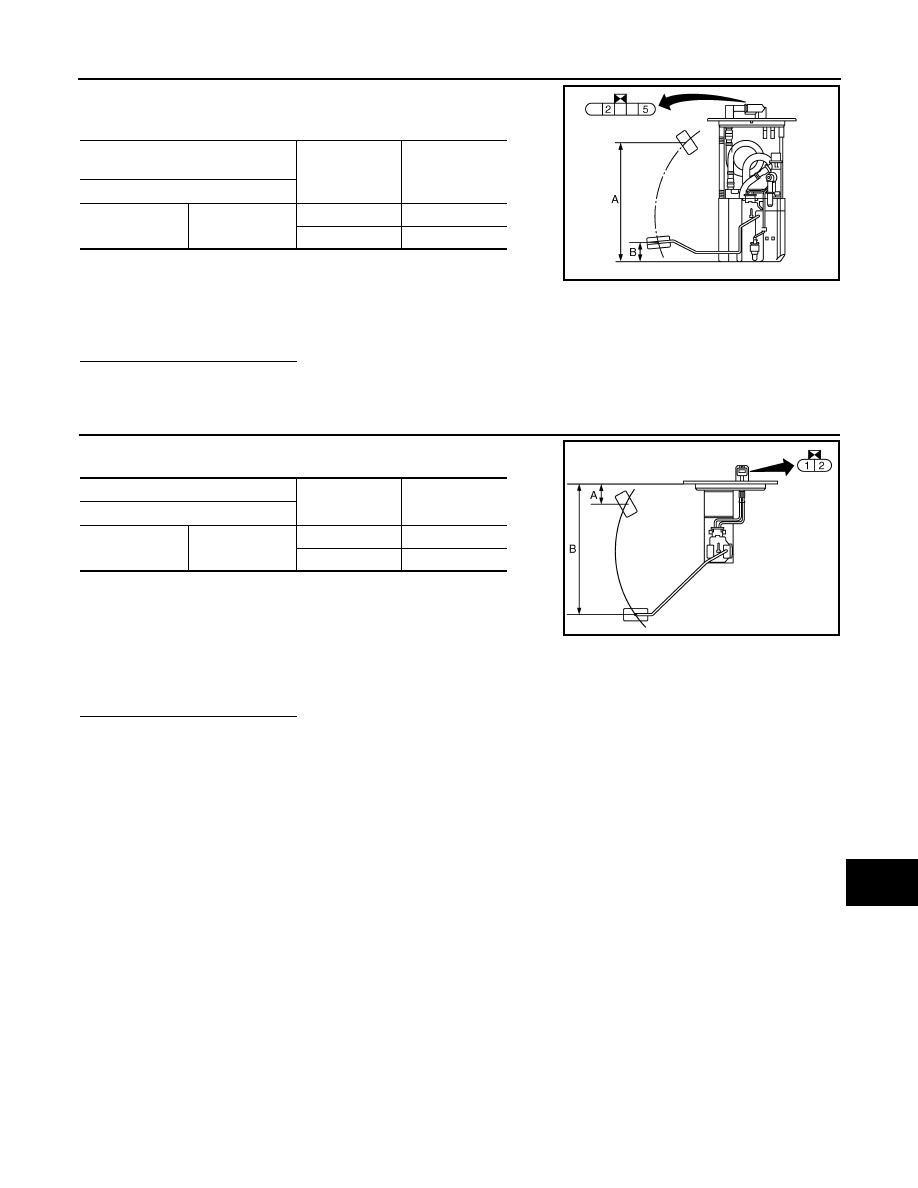
Check the resistance between fuel level sensor unit and fuel pump
(main).
Standard float position
Is the inspection result normal?
YES
>> GO TO 3.
NO
>> Replace fuel level sensor unit and fuel pump (main).
3.
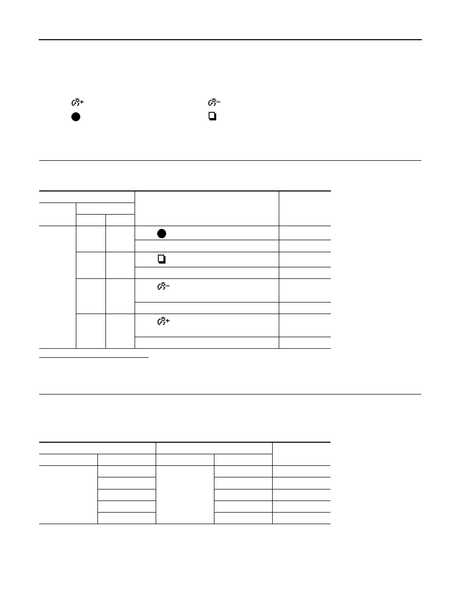
CHECK FUEL LEVEL SENSOR UNIT (SUB)
Inspect the resistance of fuel level sensor unit (sub).
Standard float position
Is the inspection result normal?
YES
>> INSPECTION END
NO
>> Replace fuel level sensor unit (sub).
Fuel level sensor unit and fuel pump
(main)
Condition
Resistance
(Approx.)
Terminal
2
5
Full
3
Ω
Empty
80
Ω
JPNIA0841ZZ
Full (A) [mm (in)]
: Approx. 194 (7.64)
Empty (B) [mm (in)]
: Approx. 30 (1.18)
Fuel level sensor unit (sub)
Condition
Resistance
(Approx.)
Terminal
1
2
Full
3
Ω
Empty
43
Ω
JPNIA0842ZZ
Full (A) [mm (in)]
: Approx. 32 (1.26)
Empty (B) [mm (in)]
: Approx. 203 (7.99)
MWI-60
< COMPONENT DIAGNOSIS >
METER CONTROL SWITCH SIGNAL CIRCUIT
METER CONTROL SWITCH SIGNAL CIRCUIT
Description
INFOID:0000000003140213
Transmits the following signals to the combination meter.
Diagnosis Procedure
INFOID:0000000003140214
1.
CHECK METER CONTROL SWITCH INPUT SIGNAL
1.
Turn the ignition switch ON.
2.
Measure voltage between the following terminals of the combination meter.
Is the inspection result normal?
YES
>> INSPECTION END
NO
>> GO TO 2.
2.
CHECK METER CONTROL SWITCH SIGNAL CIRCUIT
1.
Turn the ignition switch OFF.
2.
Disconnect the combination meter and meter control switch connectors.
3.
Check continuity between combination meter harness connector and meter control switch harness con-
nector.
4.
Check continuity between combination meter harness connector and ground.
•
(Illumination control) switch signal (+)
•
(Illumination control) switch signal (–)
•
(select) switch signal
•
(enter) switch signal
Combination meter
Condition
Voltage
Connector
Terminal
(+)
(-)
M53
36
16
When
(select) switch is pressed
0 V
Other than the above
5 V
37
16
When
(enter) switch is pressed
0 V
Other than the above
5 V
39
16
When
(illumination control) switch is
pressed
0 V
Other than the above
5 V
40
16
When
(illumination control) switch is
pressed
0 V
Other than the above
5 V
Combination meter
Meter control switch
Continuity
Connector
Terminal
Connector
Terminal
M53
16
M54
2
Existed
36
6
Existed
37
7
Existed
39
3
Existed
40
1
Existed
MWI
METER CONTROL SWITCH SIGNAL CIRCUIT
MWI-61
< COMPONENT DIAGNOSIS >
C
D
E
F
G
H
I
J
K
L
M
B
A
O
P
Is the inspection result normal?
YES
>> INSPECTION END
NO
>> Repair harness or connector.
Component Inspection
INFOID:0000000003140215
1.
CHECK METER CONTROL SWITCH UNIT
1.
Turn the ignition switch OFF.
2.
Disconnect the meter control switch connector.
3.
Check continuity between the following terminals of the meter control switch.
Is inspection result normal?
YES
>> INSPECTION END
NO
>> Replace the meter control switch.
Combination meter
Ground
Continuity
Connector
Terminal
M53
16
Not existed
36
Not existed
37
Not existed
39
Not existed
40
Not existed
Combination meter
Operation and status
Continuity
Connector
Terminal
M54
6
2
Press
(select) switch
Existed
Other than the above
Not existed
7
2
Press
(enter) switch
Existed
Other than the above
Not existed
3
2
Press
(illumination control) switch
Existed
Other than the above
Not existed
1
2
Press
(illumination control) switch
Existed
Other than the above
Not existed
Нет комментариевНе стесняйтесь поделиться с нами вашим ценным мнением.
Текст