Infiniti EX35. Manual — part 1561
WW-96
< SYMPTOM DIAGNOSIS >
NORMAL OPERATING CONDITION
NORMAL OPERATING CONDITION
Description
INFOID:0000000003591484
FRONT WIPER MOTOR PROTECTION FUNCTION
• IPDM E/R may stop the front wiper to protect the front wiper motor if any obstruction (operation resistance)
such as a large amount of snow is detected during the front wiper operation.
• At that time turn OFF the front wiper and remove the foreign object. Then wait for approximately 20 seconds
or more and reactivate the front wiper. The wiper will operate normally.
REAR WIPER MOTOR PROTECTION FUNCTION
• BCM may stop rear wiper to protect the rear wiper motor when the rear wiper is stopped for 5 seconds or
more due to a snowfall.
• Rear wiper operates normally one minute after the obstacles are removed with rear wiper OFF.

FRONT WIPER DOES NOT OPERATE
WW-97
< SYMPTOM DIAGNOSIS >
C
D
E
F
G
H
I
J
K
M
A
B
WW
N
O
P
FRONT WIPER DOES NOT OPERATE
Description
INFOID:0000000003139003
The front wiper does not operate under any operating conditions.
Diagnosis Procedure
INFOID:0000000003139004
1.
CHECK WIPER RELAY OPERATION
IPDM E/R AUTO ACTIVE TEST
1.
Start IPDM E/R auto active test. Refer to
PCS-11, "Diagnosis Description"
2.
Check that the front wiper operates at the LO/HI operation.
CONSULT-III ACTIVE TEST
1.
Select “FRONT WIPER” of IPDM E/R active test item.
2.
With operating the test item, check that front wiper LO/HI operation and OFF.
Does the front wiper operate?
YES
>> GO TO 5.
NO
>> GO TO 2.
2.
CHECK FRONT WIPER MOTOR FUSE
1.
Turn the ignition switch OFF.
2.
Check that the front wiper motor 30A (#60) fuse is not fusing.
Is the fuse fusing?
YES
>> Replace the fuse after repairing the applicable circuit.
NO
>> GO TO 3.
3.
CHECK FRONT WIPER MOTOR (GND) OPEN CIRCUIT
1.
Disconnect front wiper motor connector.
2.
Check continuity between front wiper motor harness connector and ground.
Does continuity exist?
YES
>> GO TO 4.
NO
>> Repair the harnesses or connectors.
4.
CHECK FRONT WIPER MOTOR OUTPUT VOLTAGE
CONSULT-III ACTIVE TEST
1.
Disconnect front wiper motor connector.
2.
Turn the ignition switch ON.
3.
Select “FRONT WIPER” of IPDM E/R active test item.
4.
With operating the test item, check voltage between IPDM E/R harness connector and ground.
Lo
: Front wiper LO operation
Hi
: Front wiper HI operation
Off
: Stop the front wiper.
Front wiper motor
Ground
Continuity
Connector
Terminal
E42
2
Existed

WW-98
< SYMPTOM DIAGNOSIS >
FRONT WIPER DOES NOT OPERATE
Is the measurement normal?
YES
>> Replace front wiper motor.
NO
>> Replace IPDM E/R.
5.
CHECK FRONT WIPER REQUEST SIGNAL INPUT
CONSULT-III DATA MONITOR
1.
Select “FR WIP REQ” of IPDM E/R data monitor item.
2.
Switch the front wiper switch to HI and LO.
3.
With operating the front wiper switch, check the monitor status.
Is the status of item normal?
YES
>> Replace IPDM E/R.
NO
>> GO TO 6.
6.
CHECK COMBINATION SWITCH
Perform the inspection of the combination switch. Refer to
Is combination switch normal?
YES
>> Replace BCM. Refer to
NO
>> Repair or replace the applicable parts.
Terminals
Test item
Voltage
(Approx.)
(+)
(-)
IPDM E/R
Ground
FRONT WIPER
Connector
Terminal
E5
4
Lo
Battery voltage
Off
0 V
5
Hi
Battery voltage
Off
0 V
Monitor item
Condition
Monitor status
FR WIPER REQ
Front wiper switch HI
ON
Hi
OFF
Stop
Front wiper switch LO
ON
Low
OFF
Stop
PRECAUTIONS
WW-99
< PRECAUTION >
C
D
E
F
G
H
I
J
K
M
A
B
WW
N
O
P
PRECAUTION
PRECAUTIONS
Precaution for Supplemental Restraint System (SRS) "AIR BAG" and "SEAT BELT
PRE-TENSIONER"
INFOID:0000000003139006
The Supplemental Restraint System such as “AIR BAG” and “SEAT BELT PRE-TENSIONER”, used along
with a front seat belt, helps to reduce the risk or severity of injury to the driver and front passenger for certain
types of collision. This system includes seat belt switch inputs and dual stage front air bag modules. The SRS
system uses the seat belt switches to determine the front air bag deployment, and may only deploy one front
air bag, depending on the severity of a collision and whether the front occupants are belted or unbelted.
Information necessary to service the system safely is included in the “SRS AIRBAG” and “SEAT BELT” of this
Service Manual.
WARNING:
• To avoid rendering the SRS inoperative, which could increase the risk of personal injury or death in
the event of a collision which would result in air bag inflation, all maintenance must be performed by
an authorized NISSAN/INFINITI dealer.
• Improper maintenance, including incorrect removal and installation of the SRS, can lead to personal
injury caused by unintentional activation of the system. For removal of Spiral Cable and Air Bag
Module, see the “SRS AIRBAG”.
• Do not use electrical test equipment on any circuit related to the SRS unless instructed to in this
Service Manual. SRS wiring harnesses can be identified by yellow and/or orange harnesses or har-
ness connectors.
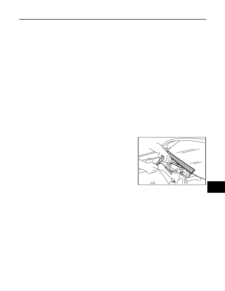
Precaution for Procedure without Cowl Top Cover
INFOID:0000000003139007
When performing the procedure after removing cowl top cover, cover
the lower end of windshield with urethane, etc.
PIIB3706J
Нет комментариевНе стесняйтесь поделиться с нами вашим ценным мнением.
Текст