Infiniti EX35. Manual — part 724
REAR TIMING CHAIN CASE
EM-95
< DISASSEMBLY AND ASSEMBLY >
C
D
E
F
G
H
I
J
K
L
M
A
EM
N
P
O
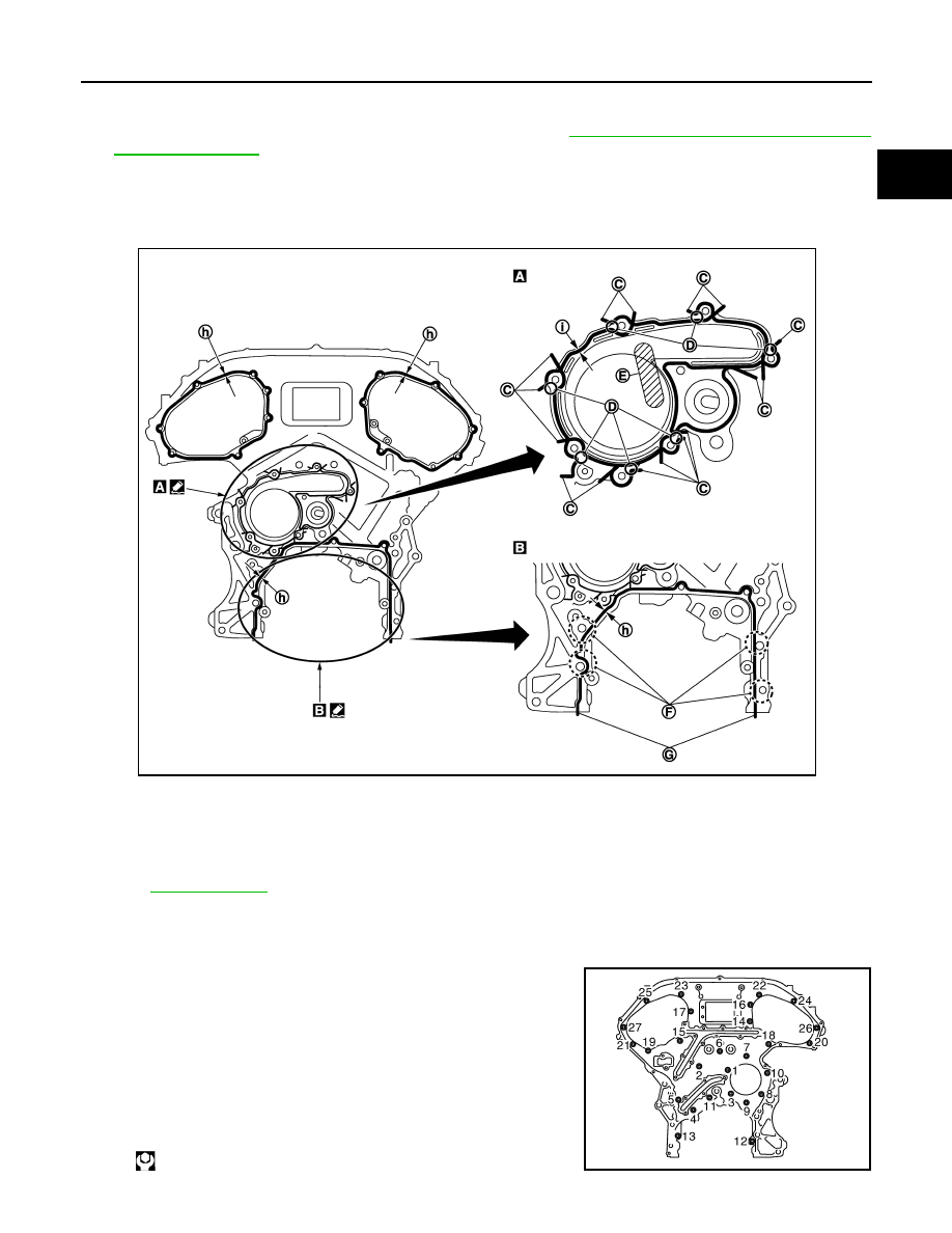
b.
Apply liquid gasket with the tube presser (commercial service tool) to rear timing chain case back side as
shown in the figure.
Use Genuine RTV Silicone Sealant or equivalent. Refer to
GI-15, "Recommended Chemical Prod-
.
CAUTION:
• For (A) in the figure, completely wipe out liquid gasket extended on a portion touching at engine
coolant.
• Apply liquid gasket on installation position of water pump and cylinder head very completely.
c.
Align rear timing chain case with dowel pins (bank 1 and bank 2) on cylinder block and install rear timing
chain case.
• Check O-rings stay in place during installation to cylinder block and cylinder head.
d.
Tighten mounting bolts in numerical order as shown in the fig-
ure.
• There are two types of mounting bolts. Refer to the following
for locating bolts.
C.
Protrusion
D.
Clearance 1 mm (0.04 in)
E.
Do not protrude in this area
F.
Run along bolt hole inner side
G.
Protrusions at beginning and end of
gasket
h.
φ
3.9 mm (0.154 in)
i.
φ
2.7 mm (0.106 in)
Refer to
for symbols in the figure.
Bolt length:
Bolt position
20 mm (0.79 in)
: 1, 2, 3, 6, 7, 8, 9, 10
16 mm (0.63 in)
: 4, 5, 11, 12, 13
: 12.7 N·m (1.3 kg-m, 9 ft-lb)
JPBIA0092ZZ
JPBIA0089ZZ

EM-96
< DISASSEMBLY AND ASSEMBLY >
REAR TIMING CHAIN CASE
e.
After all bolts are tightened, retighten them to the specified torque in numerical order shown in the figure.
• If liquid gasket protrudes, wipe it off immediately.
f.
After installing rear timing chain case, check the surface height
difference between the following parts on the oil pan (upper)
mounting surface.
• If not within the standard, repeat the installation procedure.
3.
Install water pump with new O-rings. Refer to
.
4.
Check that dowel pin (A) and crankshaft key (1) are located as
shown in the figure. (No. 1 cylinder at compression TDC)
NOTE:
Though camshaft does not stop at the position as shown in the
figure, for the placement of cam nose, it is generally accepted
camshaft is placed for the same direction of the figure.
5.
Install timing chains (secondary) and camshaft sprockets as follows:
CAUTION:
Matching marks between timing chain and sprockets slip easily. Confirm all matching mark posi-
tions repeatedly during the installation process.
a.
Push plunger of timing chain tensioner (secondary) and keep it
pressed in with a stopper pin (A).
6.
For the following operations, perform steps in the reverse order of removal.
Bolt length:
Bolt position
16 mm (0.63 in)
: Except the above
: 15.0 N·m (1.5 kg-m, 11 ft-lb)
1
: Rear timing chain case
2
: Lower cylinder block
Standard
Rear timing chain case to lower cylinder block:
–0.24 to 0.14 mm (–0.0094 to 0.0055 in)
JPBIA1363ZZ
Camshaft dowel pin
: At cylinder head upper face side in each bank.
Crankshaft key
: At cylinder head side of bank 1.
JPBIA0094ZZ
JPBIA0095ZZ
OIL PAN (UPPER) AND OIL STRAINER
EM-97
< DISASSEMBLY AND ASSEMBLY >
C
D
E
F
G
H
I
J
K
L
M
A
EM
N
P
O
OIL PAN (UPPER) AND OIL STRAINER
2WD
2WD : Exploded View
INFOID:0000000003139137
2WD : Disassembly and Assembly
INFOID:0000000003139138
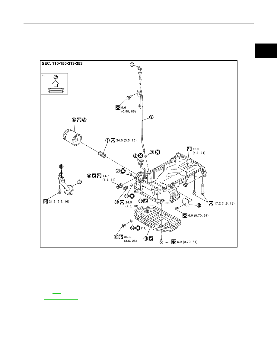
REMOVAL
CAUTION:
Never drain engine oil when the engine is hot to avoid the danger of being scalded.
1.
Remove oil level gauge, oil pressure switch and oil temperature sensor.
1.
Oil level gauge
2.
Oil level gauge guide
3.
O-ring
4.
O-ring
5.
Connector bolt
6.
Oil filter
7.
Plug
8.
Oil pressure switch
9.
Oil strainer
10. Oil temperature sensor
11.
Washer
12. Oil pan (upper)
13. Drain plug
14. Drain plug washer
15. Oil pan (lower)
16. Rear plate cover
A.
Refer to
B.
To oil pump
C.
Oil pan side
Refer to
for symbols in the figure.
JPBIA0530GB
EM-98
< DISASSEMBLY AND ASSEMBLY >
OIL PAN (UPPER) AND OIL STRAINER
2.
Remove oil pan (lower). Refer to
3.
Remove oil strainer.
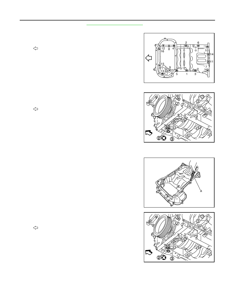
4.
Loosen mounting bolts in the reverse order as shown in the fig-
ure with power tool to remove.
• Insert the seal cutter [SST: KV10111100 (J37228)] between oil
pan (upper) and lower cylinder block. Slide seal cutter by tap-
ping on the side of tool with a hammer. Remove oil pan
(upper).
CAUTION:
• Be careful not to damage the mating surfaces.
• Never insert a screwdriver, this will damage the mating
surfaces.
5.
Remove o-rings (2) from bottom of lower cylinder block (1) and
oil pump (3).
INSTALLATION
1.
Install oil pan (upper) as follows:
a.
Use a scraper (A) to remove old liquid gasket from mating sur-
faces.
CAUTION:
Never scratch or damage the mating surfaces when clean-
ing off old liquid gasket.
• Also remove old liquid gasket from mating surface of lower cyl-
inder block.
• Remove old liquid gasket from the bolt holes and threads.
b.
Install new O-rings (2) on the bottom of lower cylinder block (1)
and oil pump (3).
: Engine front
JPBIA0022ZZ
: Engine front
JPBIA1330ZZ
JPBIA0027ZZ
: Engine front
JPBIA1330ZZ
Нет комментариевНе стесняйтесь поделиться с нами вашим ценным мнением.
Текст