Infiniti EX35. Manual — part 197

AV
STEERING ANGLE SENSOR SIGNAL CIRCUIT
AV-569
< COMPONENT DIAGNOSIS >
[BOSE AUDIO WITH NAVIGATION]
C
D
E
F
G
H
I
J
K
L
M
B
A
O
P
4.
Check continuity between around view monitor control unit harness connector and ground.
Is inspection result normal?
YES
>> GO TO 2.
NO
>> Repair harness or connector.
2.
CHECK SIGNAL SENSOR SIGNAL
1.
Connect around view monitor control unit connector.
2.
Turn ignition switch ON.
3.
Check voltage between around view monitor control unit harness connector and ground.
Is inspection result normal?
YES
>> GO TO 3.
NO
>> Replace around view monitor control unit.
3.
CHECK SIGNAL SENSOR SIGNAL
1.
Turn ignition switch OFF.
2.
Connect steering angle sensor connector.
3.
Turn ignition switch ON.
4.
Check signal between around view monitor control unit harness connector and ground.
Around view monitor control
unit
Steering angle sensor
Continuity
Connector
Terminals
Connector
Terminals
B46
14
M37
3
Existed
15
4
16
5
Around view monitor control
unit
Ground
Continuity
Connector
Terminals
B46
14
Not existed
15
16
(+)
(
−
)
Voltage
(Approx.)
Around view monitor control
unit
Connector
Terminals
B46
14
Ground
5.0 V
15
16
AV-570
< COMPONENT DIAGNOSIS >
[BOSE AUDIO WITH NAVIGATION]
STEERING ANGLE SENSOR SIGNAL CIRCUIT
Is inspection result normal?
YES
>> INSPECTION END
NO
>> Replace steering angle sensor.
(+)
(
−
)
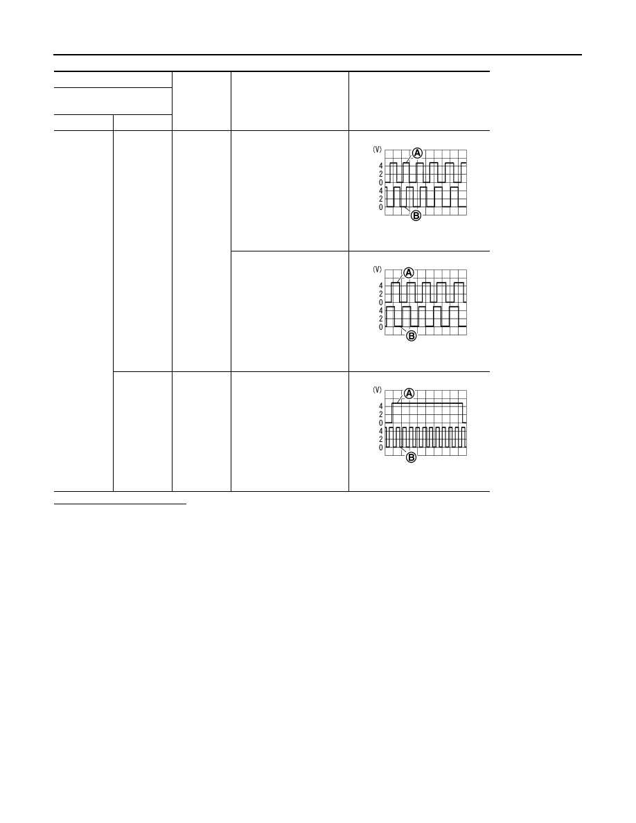
Condition
Reference value
Around view monitor control
unit
Connector
Terminals
B46
14, 15
Ground
Turn the steering to the right
A: Sensor signal 1
B: Sensor signal 2
Turn the steering to the left
A: Sensor signal 1
B: Sensor signal 2
16
Ground
Turn the steering around the
neutral position
A: Sensor signal 3
B: Sensor signal 1
SKIB3827E
SKIB3828E
SKIB3829E
AV
STEERING SWITCH SIGNAL A CIRCUIT
AV-571
< COMPONENT DIAGNOSIS >
[BOSE AUDIO WITH NAVIGATION]
C
D
E
F
G
H
I
J
K
L
M
B
A
O
P
STEERING SWITCH SIGNAL A CIRCUIT
Description
INFOID:0000000003160731
Transmits the steering switch signal to AV control unit.
Diagnosis Procedure
INFOID:0000000003160732
1.
CHECK STEERING SWITCH SIGNAL A CIRCUIT
1.
Disconnect AV control unit connector and spiral cable connector.
2.
Check continuity between AV control unit harness connector and spiral cable harness connector.
3.
Check continuity between AV control unit harness connector and ground.
Is inspection result normal?
YES
>> GO TO 2.
NO
>> Repair harness or connector.
2.
CHECK SPIRAL CABLE
Check spiral cable.
Is inspection result normal?
YES
>> GO TO 3.
NO
>> Replace spiral cable.
3.
CHECK AV CONTROL UNIT VOLTAGE
1.
Connect AV control unit connector and spiral cable connector.
2.
Turn ignition switch ON.
3.
Check voltage between AV control unit harness connector.
Is inspection result normal?
YES
>> GO TO 4.
NO
>> Replace AV control unit.
4.
CHECK STEERING SWITCH
1.
Turn ignition switch OFF.
2.
Check steering switch. Refer to
AV-572, "Component Inspection"
Is inspection result normal?
YES
>> INSPECTION END
NO
>> Replace steering switch.
AV control unit
Spiral cable
Continuity
Connector
Terminal
Connector
Terminal
M80
6
M36
24
Existed
AV control unit
Ground
Continuity
Connector
Terminal
M80
6
Not existed
(+)
(
−
)
Voltage
(Approx.)
AV control unit
AV control unit
Connector
Terminal
Connector
Terminal
M80
6
M80
15
5.0 V
AV-572
< COMPONENT DIAGNOSIS >
[BOSE AUDIO WITH NAVIGATION]
STEERING SWITCH SIGNAL A CIRCUIT
Component Inspection
INFOID:0000000003160733
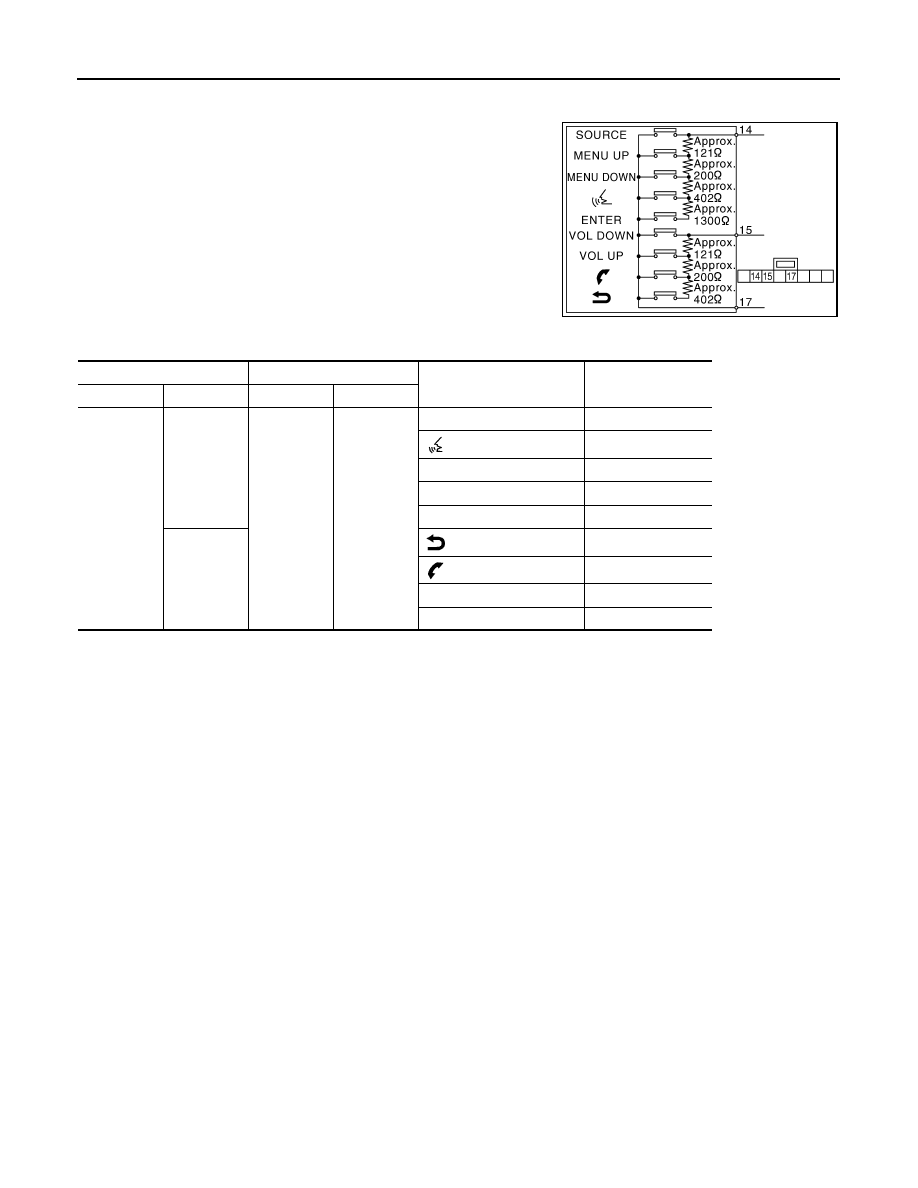
Measure the resistance between the steering switch connector.
JSNIA0112GB
Steering switch
Steering switch
Condition
Resistance value
(
Ω
)
Connector
Terminal
Connector
Terminal
M303
14
M303
17
ENTER switch ON
2003 – 2043
switch ON
716 – 730
MENU DOWN switch ON
318 – 324
MENU UP switch ON
120 – 122
SOURCE switch ON
0
15
switch ON
716 – 730
switch ON
318 – 324
VOL UP switch ON
120 – 122
VOL DOWN switch ON
0
Нет комментариевНе стесняйтесь поделиться с нами вашим ценным мнением.
Текст