Infiniti EX35. Manual — part 195
AV
MICROPHONE SIGNAL CIRCUIT
AV-561
< COMPONENT DIAGNOSIS >
[BOSE AUDIO WITH NAVIGATION]
C
D
E
F
G
H
I
J
K
L
M
B
A
O
P
Is inspection result normal?
YES
>> Replace AV control unit.
NO
>> Replace microphone.
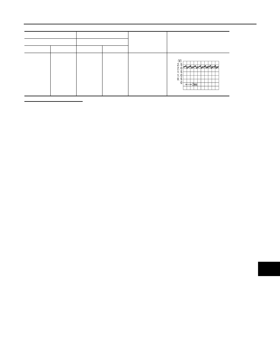
(+)
(
−
)
Condition
Reference value
AV control unit
AV control unit
Connector
Terminal
Connector
Terminal
M87
28
M87
27
give a voice.
PKIB5037J

AV-562
< COMPONENT DIAGNOSIS >
[BOSE AUDIO WITH NAVIGATION]
REAR VIEW CAMERA IMAGE SIGNAL CIRCUIT
REAR VIEW CAMERA IMAGE SIGNAL CIRCUIT
Description
INFOID:0000000003513843
• Camera control unit outputs camera ON signal to rear view camera and inputs rear view camera image sig-
nal from rear view camera when the reverse signal is input.
• The camera control unit that inputs the camera image signal transmits the camera image signal to the dis-
play unit.
Diagnosis Procedure
INFOID:0000000003369310
1.
CHECK CONTINUITY CAMERA POWER SUPPLY CIRCUIT
1.
Turn ignition switch OFF.
2.
Disconnect camera control unit connector and rear view camera connector.
3.
Check continuity between camera control unit harness connector and rear view camera harness connec-
tor.
4.
Check continuity between camera control unit harness connector and ground.
Is inspection result normal?
YES
>> GO TO 2.
NO
>> Repair harness or connector.
2.
CHECK VOLTAGE CAMERA POWER SUPPLY
1.
Connect camera control unit connector and rear view camera connector.
2.
Turn ignition switch ON.
3.
Shift position is “R”
4.
Check voltage between camera control unit harness connector and ground.
Is inspection result normal?
YES
>> GO TO 3.
NO
>> Replace camera control unit.
3.
CHECK CONTINUITY CAMERA IMAGE SIGNAL CIRCUIT
1.
Turn ignition switch OFF.
2.
Disconnect camera control unit connector and rear view camera connector.
3.
Check continuity between camera control unit harness connector and rear view camera harness connec-
tor.
4.
Check continuity between camera control unit harness connector and ground.
Camera control unit
Rear view camera
Continuity
Connector
Terminal
Connector
Terminal
B50
8
D121
1
Existed
Camera control unit
Ground
Continuity
Connector
Terminal
B50
8
Not existed
(+)
(
−
)
Condition
Voltage
(Approx.)
Camera control unit
Connector
Terminal
B50
8
Ground
Shift position is “R”
6.0 V
Camera control unit
Rear view camera
Continuity
Connector
Terminal
Connector
Terminal
B50
6
D121
3
Existed
AV
REAR VIEW CAMERA IMAGE SIGNAL CIRCUIT
AV-563
< COMPONENT DIAGNOSIS >
[BOSE AUDIO WITH NAVIGATION]
C
D
E
F
G
H
I
J
K
L
M
B
A
O
P
Is inspection result normal?
YES
>> GO TO 4.
NO
>> Repair harness or connector.
4.
CHECK CAMERA IMAGE SIGNAL
1.
Connect camera control unit connector and rear view camera connector.
2.
Turn ignition switch ON.
3.
Shift position is “R”
4.
Check signal between camera control unit harness connector and ground.
Is inspection result normal?
YES
>> Replace camera control unit.
NO
>> Replace rear view camera.
Camera control unit
Ground
Continuity
Connector
Terminal
B50
6
Not existed
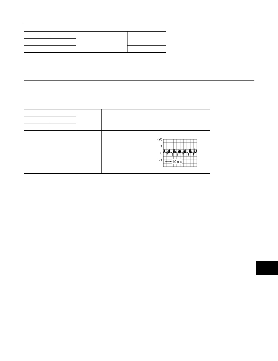
(+)
(
−
)
Condition
Reference value
Camera control unit
Connector
Terminal
B50
6
Ground
Shift position is “R”
JSNIA0834GB

AV-564
< COMPONENT DIAGNOSIS >
[BOSE AUDIO WITH NAVIGATION]
CAMERA IMAGE SIGNAL CIRCUIT
CAMERA IMAGE SIGNAL CIRCUIT
WITH REAR VIEW MONITOR
WITH REAR VIEW MONITOR : Description
INFOID:0000000003160725
• Camera control unit outputs camera ON signal to rear view camera and inputs rear view camera image sig-
nal from rear view camera when the reverse signal is input.
• The camera control unit that inputs the camera image signal transmits the camera image signal to the dis-
play unit.
WITH REAR VIEW MONITOR : Diagnosis Procedure
INFOID:0000000003160726
1.
CHECK CONTINUITY CAMERA IMAGE SIGNAL CIRCUIT
1.
Turn ignition switch OFF.
2.
Disconnect camera control unit connector and display unit connector.
3.
Check continuity between camera control unit harness connector and display unit harness connector.
4.
Check continuity between camera control unit harness connector and ground.
Is inspection result normal?
YES
>> GO TO 2.
NO
>> Repair harness or connector.
2.
CHECK CAMERA IMAGE SIGNAL
1.
Connect camera control unit connector and display unit connector.
2.
Turn ignition switch ON.
3.
Shift position is “R”.
4.
Check signal between camera control unit harness connector and ground.
Is inspection result normal?
YES
>> Replace display unit.
NO
>> Replace camera control unit.
WITH AROUND VIEW MONITOR
Camera control unit
Display unit
Continuity
Connector
Terminal
Connector
Terminal
B50
12
M75
12
Existed
Camera control unit
Ground
Continuity
Connector
Terminal
B50
12
Not existed
(+)
(
−
)
Condition
Reference value
Camera control unit
Connector
Terminal
B50
12
Ground
Shift position is “R”
JSNIA0834GB
Нет комментариевНе стесняйтесь поделиться с нами вашим ценным мнением.
Текст