Infiniti EX35. Manual — part 196
AV
CAMERA IMAGE SIGNAL CIRCUIT
AV-565
< COMPONENT DIAGNOSIS >
[BOSE AUDIO WITH NAVIGATION]
C
D
E
F
G
H
I
J
K
L
M
B
A
O
P
WITH AROUND VIEW MONITOR : Description
INFOID:0000000003513842
• Around view monitor control unit supplies to the front camera, rear camera and side camera. And then it
superimpose the images from each camera and outputs then to the display unit.
• Superimpose the guiding lines, predicted course line and sonar indicator to the camera image that outputs to
the display unit.
• Around view monitor control unit performs the reception/transmission of communication signal with each
camera.
WITH AROUND VIEW MONITOR : Diagnosis Procedure
INFOID:0000000003415753
1.
CHECK CONTINUITY CAMERA IMAGE SIGNAL CIRCUIT
1.
Turn ignition switch OFF.
2.
Disconnect around view monitor control unit connector and display unit connector.
3.
Check continuity between around view monitor control unit harness connector and display unit harness
connector.
4.
Check continuity between around view monitor control unit harness connector and ground.
Is inspection result normal?
YES
>> GO TO 2.
NO
>> Repair harness or connector.
2.
CHECK CAMERA IMAGE SIGNAL
1.
Connect around view monitor control unit connector and display unit connector.
2.
Turn ignition switch ON.
3.
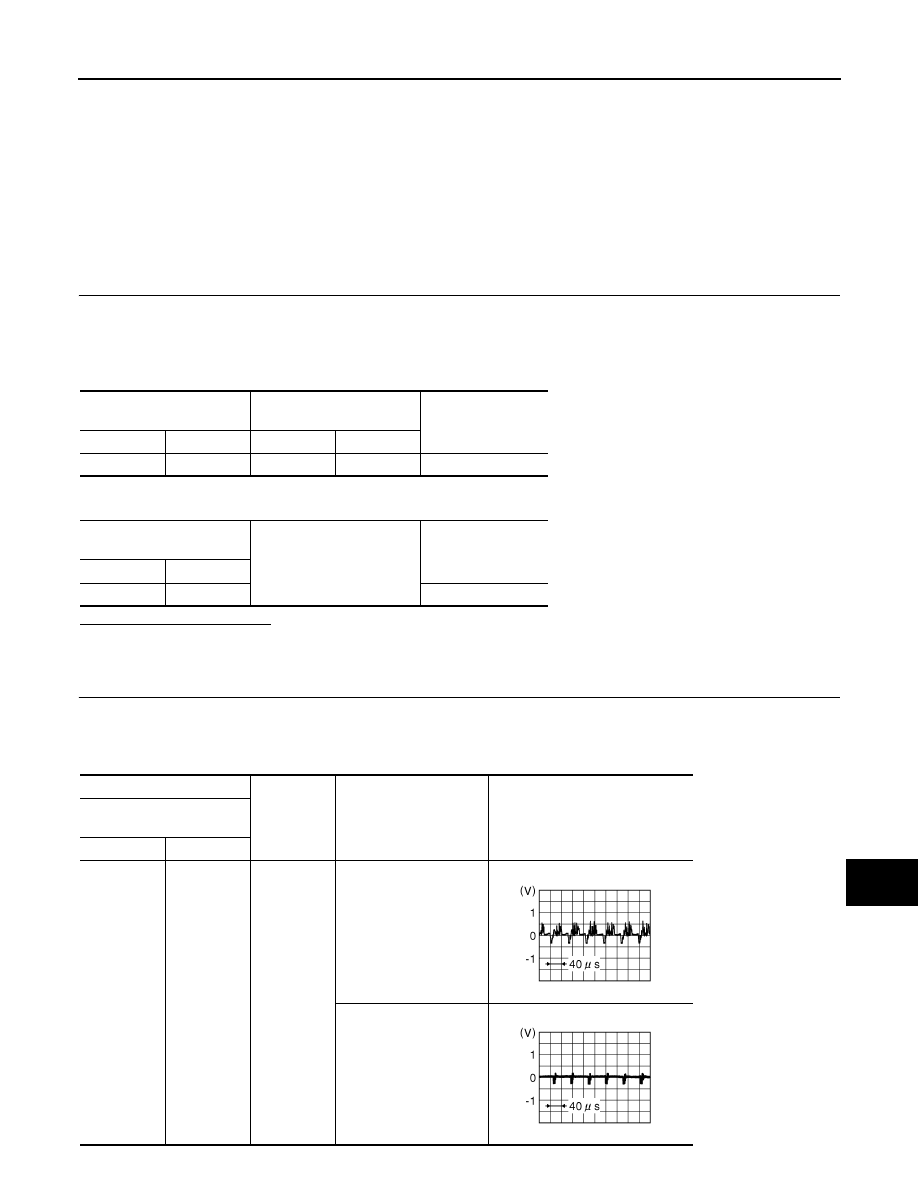
Check signal between around view monitor control unit harness connector and ground.
Around view monitor control
unit
display unit
Continuity
Connector
Terminal
Connector
Terminal
B46
27
M75
12
Existed
Around view monitor control
unit
Ground
Continuity
Connector
Terminal
B46
27
Not existed
(+)
(
−
)
Condition
Reference value
Around view monitor control
unit
Connector
Terminal
B46
27
Ground
At camera image display
Other than camera im-
age display
JSNIA0834GB
JSNIA0835GB
AV-566
< COMPONENT DIAGNOSIS >
[BOSE AUDIO WITH NAVIGATION]
CAMERA IMAGE SIGNAL CIRCUIT
Is inspection result normal?
YES
>> Replace display unit.
NO
>> Replace around view monitor control unit.
AV
STEERING ANGLE SENSOR SIGNAL CIRCUIT
AV-567
< COMPONENT DIAGNOSIS >
[BOSE AUDIO WITH NAVIGATION]
C
D
E
F
G
H
I
J
K
L
M
B
A
O
P
STEERING ANGLE SENSOR SIGNAL CIRCUIT
WITH REAR VIEW MONITOR
WITH REAR VIEW MONITOR : Description
INFOID:0000000003160727
• Steering angle sensor signal 1, 2 detects the turning direction and quantity of the steering and transmits it to
the camera control unit.
• Steering angle sensor signal 3 detects the neutral position of the steering and transmits it to the camera con-
trol unit.
• Camera control unit performs the correction of neutral position with sensor signal 1, 2, 3 and vehicle speed
signal.
WITH REAR VIEW MONITOR : Diagnosis Procedure
INFOID:0000000003160728
1.
CHECK CONTINUITY STEERING ANGLE SENSOR SIGNAL CIRCUIT
1.
Turn ignition switch OFF.
2.
Disconnect camera control unit connector and steering angle sensor connector.
3.
Check continuity between camera control unit harness connector and steering angle sensor harness con-
nector.
4.
Check continuity between camera control unit harness connector and ground.
Is inspection result normal?
YES
>> GO TO 2.
NO
>> Repair harness or connector.
2.
CHECK SIGNAL SENSOR SIGNAL
1.
Connect camera control unit connector.
2.
Turn ignition switch ON.
3.
Check voltage between camera control unit harness connector and ground.
Is inspection result normal?
YES
>> GO TO 3.
NO
>> Replace camera control unit.
3.
CHECK SIGNAL SENSOR SIGNAL
Camera control unit
Steering angle sensor
Continuity
Connector
Terminals
Connector
Terminals
B50
23
M37
3
Existed
24
4
25
5
Camera control unit
Ground
Continuity
Connector
Terminals
B50
23
Not existed
24
25
(+)
(
−
)
Voltage
(Approx.)
Camera control unit
Connector
Terminals
B50
23
Ground
5.0 V
24
25
AV-568
< COMPONENT DIAGNOSIS >
[BOSE AUDIO WITH NAVIGATION]
STEERING ANGLE SENSOR SIGNAL CIRCUIT
1.
Turn ignition switch OFF.
2.
Connect steering angle sensor connector.
3.
Turn ignition switch ON.
4.
Check signal between camera control unit harness connector and ground.
Is inspection result normal?
YES
>> INSPECTION END
NO
>> Replace steering angle sensor.
WITH AROUND VIEW MONITOR
WITH AROUND VIEW MONITOR : Description
INFOID:0000000003514103
• Steering angle sensor signal 1, 2 detects the turning direction and quantity of the steering and transmits it to
the around view monitor control unit.
• Steering angle sensor signal 3 detects the neutral position of the steering and transmits it to around view
monitor control unit.
• Around view monitor control unit performs the correction of neutral position with sensor signal 1, 2, 3 and
vehicle speed signal.
WITH AROUND VIEW MONITOR : Diagnosis Procedure
INFOID:0000000003514104
1.
CHECK CONTINUITY STEERING ANGLE SENSOR SIGNAL CIRCUIT
1.
Turn ignition switch OFF.
2.
Disconnect around view monitor control unit connector and steering angle sensor connector.
3.
Check continuity between around view monitor control unit harness connector and steering angle sensor
harness connector.
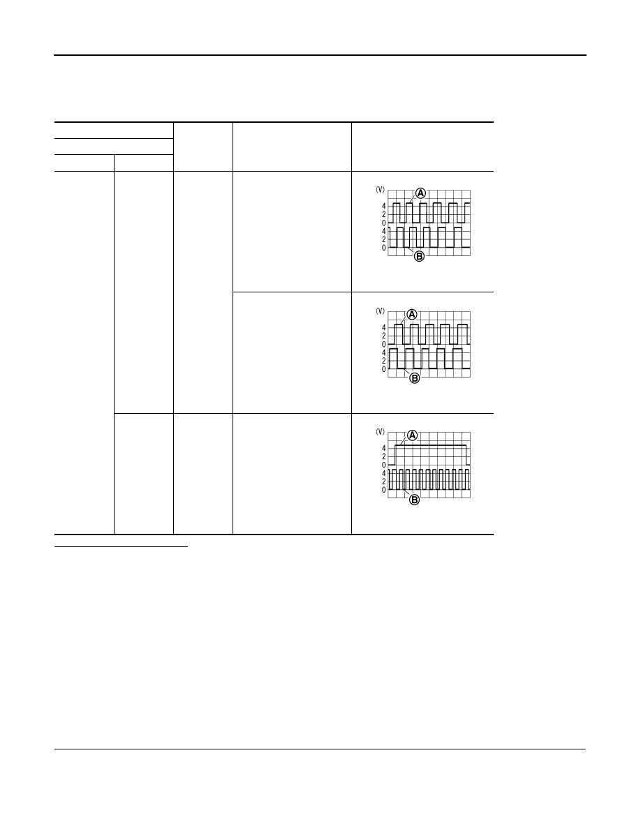
(+)
(
−
)
Condition
Reference value
Camera control unit
Connector
Terminals
B50
23, 24
Ground
Turn the steering to the right
A: Sensor signal 1
B: Sensor signal 2
Turn the steering to the left
A: Sensor signal 1
B: Sensor signal 2
25
Ground
Turn the steering around the
neutral position
A: Sensor signal 3
B: Sensor signal 1
SKIB3827E
SKIB3828E
SKIB3829E
Нет комментариевНе стесняйтесь поделиться с нами вашим ценным мнением.
Текст