Infiniti EX35. Manual — part 106

AV
DIAGNOSIS SYSTEM (TEL ADAPTER UNIT)
AV-205
< FUNCTION DIAGNOSIS >
[BOSE AUDIO WITHOUT NAVIGATION]
C
D
E
F
G
H
I
J
K
L
M
B
A
O
P
DIAGNOSIS SYSTEM (TEL ADAPTER UNIT)
Diagnosis Description
INFOID:0000000003508664
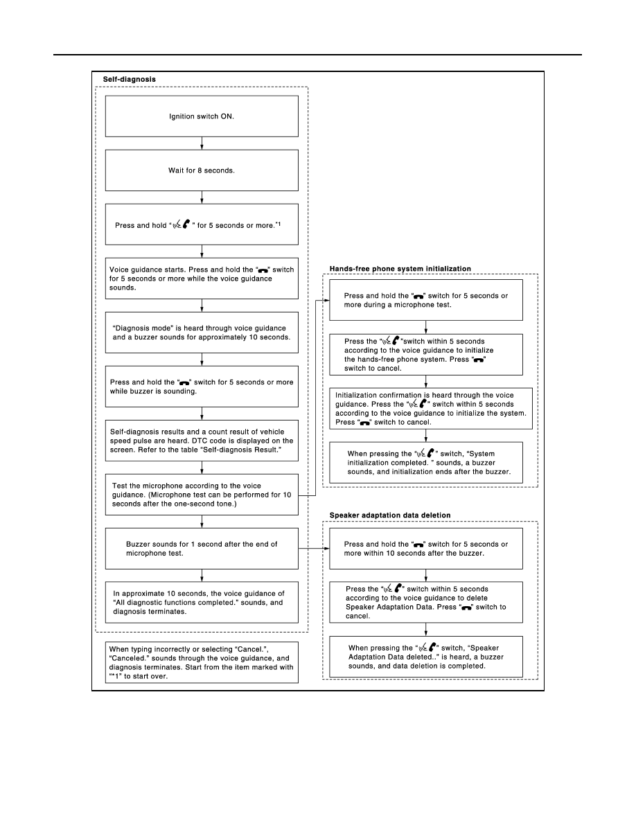
HANDS-FREE PHONE SYSTEM ON BOARD DIAGNOSIS
During on board diagnosis the diagnosis function of TEL adapter unit starts with the operation of steering
switch and performs the diagnosis when ignition switch is turned to ACC.
On board diagnosis item
The on board diagnosis has 3 modes: the self-diagnosis mode that performs the trouble diagnosis, the
speaker adaptation data deleting mode and the hands-free phone system initialization mode.
CAUTION:
• Perform the diagnosis with the vehicle stopped.
• Perform STEP2 if necessary.
Self-diagnosis results
Self-diagnosis mode reads out the self-diagnosis results and indicates DTC on the display.
NOTE:
• Error count is read out simultaneously when reading out the DTC name.
• The errors are read out continuously when some errors occur at the same time. The DTC displays are com-
bined and displayed. For example, DTC 01100 is displayed when DTC 01000 and DTC 00100 are indicated
at the same time.
Self-diagnosis results
The details of error count
The error count displays "0" when an error occurs. The next time it counts up to "1" if conditions are normal
with the ignition switch ON. It continues the count up unless the initialization of hands-free phone system is
performed.
STEP
MODE
Description
STEP1
Self-diagnosis
• The self-diagnosis mode performs the microphone test.
• The self-diagnosis mode also diagnoses TEL adapter
unit, TEL antenna and steering switch.
• Those results are indicated with voice guidance and dis-
played on the screen.
STEP2
Speaker adaptation data deleting
The speaker adaptation data deleting mode can delete the
speaker adaptation data.
Hands-free phone system initialization
Hands-free phone system initialization mode can perform
the initialization of the hands-free phone system.
DTC
DTC name
Possible causes
DTC 10000
INTERNAL FAILURE
TEL adapter unit
DTC 01000
ANT. SHORT TO BATT OR OPEN
TEL antenna
DTC 00100
ANT. SHORT TO GROUND
DTC 00010
STEERING REMOTE BUTTON STUCK A
Steering switch
DTC 00001
STEERING REMOTE BUTTON STUCK B
DTC 00000
THERE ARE NO FAILURE RECORDS TO REPORT
—
AV-206
< FUNCTION DIAGNOSIS >
[BOSE AUDIO WITHOUT NAVIGATION]
DIAGNOSIS SYSTEM (TEL ADAPTER UNIT)
FLOW CHART OF TROUBLE DIAGNOSIS
JSNIA1235GB

AV
U1000 CAN COMM CIRCUIT
AV-207
< COMPONENT DIAGNOSIS >
[BOSE AUDIO WITHOUT NAVIGATION]
C
D
E
F
G
H
I
J
K
L
M
B
A
O
P
COMPONENT DIAGNOSIS
U1000 CAN COMM CIRCUIT
Description
INFOID:0000000003544741
CAN (Controller Area Network) is a serial communication line for real-time application. It is an on-vehicle mul-
tiplex communication line with high data communication speed and excellent error detection ability. Many elec-
tronic control units are equipped onto a vehicle, and each control unit shares information and links with other
control units during operation (not independently). In CAN communication, control units are connected with 2
communication lines (CAN-H, CAN-L) allowing a high rate of information transmission with less wiring. Each
control unit transmits/receives data but selectively reads required data only.
CAN Communication Signal Chart. Refer to
LAN-27, "CAN System Specification Chart"
DTC Logic
INFOID:0000000003544742
DTC DETECTION LOGIC
Diagnosis Procedure
INFOID:0000000003544743
1.
PERFORM SELF-DIAGNOSTIC
1.
Turn ignition switch ON and wait for 2 seconds or more.
2.
Check “Self Diagnostic Result” of “MULTI AV”.
Is “CAN COMM CIRCUIT” displayed?
YES
>> Refer to “LAN system”. Refer to
LAN-18, "Trouble Diagnosis Flow Chart"
NO
>> Refer to GI section. Refer to
GI-38, "Intermittent Incident"
.
DTC
Display contents of CON-
SULT-III
Diagnostic item is detected when ...
Probable malfunction location
U1000
CAN COMM CIRCUIT
AV control unit is not transmitting or receiving
CAN communication signal for 2 seconds or
more.
CAN communication system.

AV-208
< COMPONENT DIAGNOSIS >
[BOSE AUDIO WITHOUT NAVIGATION]
U1010 CONTROL UNIT (CAN)
U1010 CONTROL UNIT (CAN)
Description
INFOID:0000000003544744
Initial diagnosis of AV control unit.
DTC Logic
INFOID:0000000003544745
DTC DETECTION LOGIC
Diagnosis Procedure
INFOID:0000000003544746
1.
REPLACE AV CONTROL UNIT
When DTC U1010 is detected, replace AV control unit.
>> INSPECTION END
DTC
Display contents of CON-
SULT-III
Diagnostic item is detected when ...
Probable malfunction location
U1010
CONTROL UNIT (CAN)
CAN initial diagnosis malfunction is detected.
AV control unit.
Нет комментариевНе стесняйтесь поделиться с нами вашим ценным мнением.
Текст