Infiniti EX35. Manual — part 608
EC-174
< COMPONENT DIAGNOSIS >
[VQ35HR]
P0117, P0118 ECT SENSOR
Component Inspection
INFOID:0000000003133335
1.
CHECK ENGINE COOLANT TEMPERATURE SENSOR
1.
Turn ignition switch OFF.
2.
Disconnect engine coolant temperature sensor harness connector.
3.
Remove engine coolant temperature sensor.
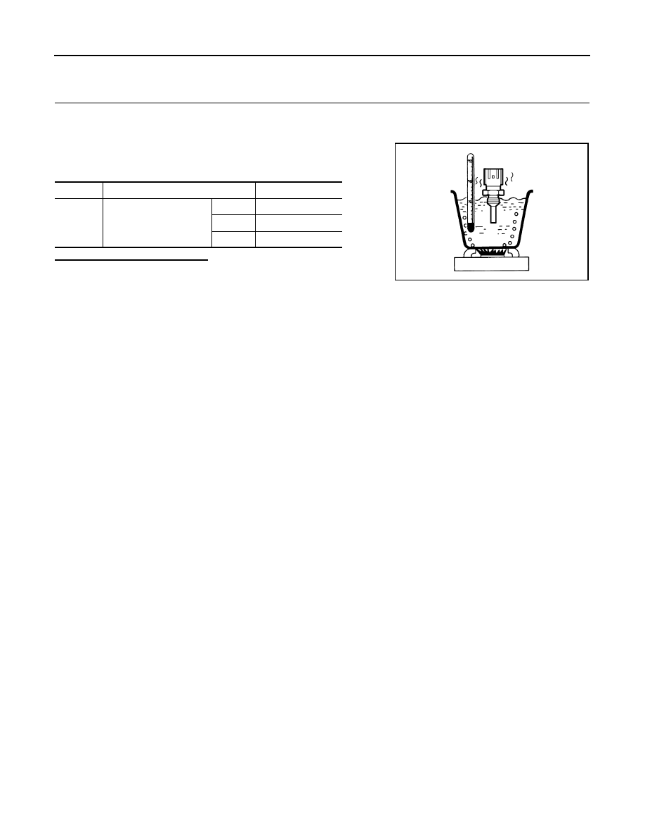
4.
Check resistance between engine coolant temperature sensor
terminals by heating with hot water as shown in the figure.
Is the inspection result normal?
YES
>> INSPECTION END
NO
>> Replace engine coolant temperature sensor.
Terminals
Condition
Resistance (k
Ω
)
1 and 2
Temperature [
°
C (
°
F)]
20 (68)
2.37 - 2.63
50 (122)
0.68 - 1.00
90 (194)
0.236 - 0.260
JMBIA0080ZZ
P0122, P0123, P0227, P0228 TP SENSOR
EC-175
< COMPONENT DIAGNOSIS >
[VQ35HR]
C
D
E
F
G
H
I
J
K
L
M
A
EC
N
P
O
P0122, P0123, P0227, P0228 TP SENSOR
Description
INFOID:0000000003133336
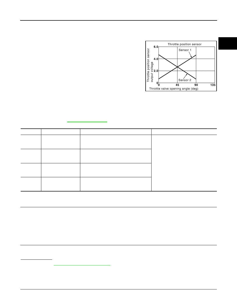
Electric throttle control actuator consists of throttle control motor,
throttle position sensor, etc. The throttle position sensor responds to
the throttle valve movement.
The throttle position sensor has two sensors. These sensors are a
kind of potentiometers which transform the throttle valve position into
output voltage, and emit the voltage signal to the ECM. In addition,
these sensors detect the opening and closing speed of the throttle
valve and feed the voltage signals to the ECM. The ECM judges the
current opening angle of the throttle valve from these signals and the
ECM controls the throttle control motor to make the throttle valve
opening angle properly in response to driving condition.
DTC Logic
INFOID:0000000003133337
DTC DETECTION LOGIC
NOTE:
If DTC P0122, P0123, P0227 or P0228 is displayed with DTC P0643, first perform the trouble diagnosis
for DTC P0643. Refer to
.
DTC CONFIRMATION PROCEDURE
1.
PRECONDITIONING
If DTC Confirmation Procedure has been previously conducted, always turn ignition switch OFF and wait at
least 10 seconds before conducting the next test.
TESTING CONDITION:
Before performing the following procedure, confirm that battery voltage is more than 10V at idle.
>> GO TO 2.
2.
PERFORM DTC CONFIRMATION PROCEDURE
1.
Start engine and let it idle for 1 second.
2.
Check DTC.
Is DTC detected?
YES
>> Go to
NO
>> INSPECTION END
Diagnosis Procedure
INFOID:0000000003133338
1.
CHECK GROUND CONNECTION
1.
Turn ignition switch OFF.
PBIB0145E
DTC No.
Trouble diagnosis name
DTC detecting condition
Possible cause
P0122
Throttle position sensor
2 (bank 1) circuit low in-
put
An excessively low voltage from the TP sensor
2 is sent to ECM.
• Harness or connectors
(TP sensor 2 circuit is open or shorted.)
• Electric throttle control actuator
(TP sensor 2)
P0123
Throttle position sensor
2 (bank 1) circuit high in-
put
An excessively high voltage from the TP sensor
2 is sent to ECM.
P0227
Throttle position sensor
2 (bank 2) circuit low in-
put
An excessively low voltage from the TP sensor
2 is sent to ECM.
P0228
Throttle position sensor
2 (bank 2) circuit high in-
put
An excessively high voltage from the TP sensor
2 is sent to ECM.

EC-176
< COMPONENT DIAGNOSIS >
[VQ35HR]
P0122, P0123, P0227, P0228 TP SENSOR
2.
Check ground connection M95. Refer to Ground Inspection in
Is the inspection result normal?
YES
>> GO TO 2.
NO
>> Repair or replace ground connection.
2.
CHECK THROTTLE POSITION SENSOR 2 POWER SUPPLY CIRCUIT-I
1.
Disconnect electric throttle control actuator harness connector.
2.
Turn ignition switch ON.
3.
Check the voltage between electric throttle control actuator harness connector and ground.
Is the inspection result normal?
YES
>> GO TO 3.
NO
>> Repair open circuit or short to ground or short to power in harness or connectors.
3.
CHECK THROTTLE POSITION SENSOR 2 GROUND CIRCUIT FOR OPEN AND SHORT
1.
Turn ignition switch OFF.
2.
Disconnect ECM harness connector.
3.
Check the continuity between electric throttle control actuator harness connector and ECM harness con-
nector.
4.
Also check harness for short to ground and short to power.
Is the inspection result normal?
YES
>> GO TO 4.
NO
>> Repair open circuit or short to ground or short to power in harness or connectors.
4.
CHECK THROTTLE POSITION SENSOR 2 INPUT SIGNAL CIRCUIT FOR OPEN AND SHORT
1.
Check the continuity between electric throttle control actuator harness connector and ECM harness con-
nector.
2.
Also check harness for short to ground and short to power.
Is the inspection result normal?
YES
>> GO TO 5.
NO
>> Repair open circuit or short to ground or short to power in harness or connectors.
5.
CHECK THROTTLE POSITION SENSOR
EC-177, "Component Inspection"
Is the inspection result normal?
YES
>> GO TO 7.
NO
>> GO TO 6.
6.
REPLACE ELECTRIC THROTTLE CONTROL ACTUATOR
DTC
Electric throttle control actuator
Ground
Voltage (V)
Bank
Connector
Terminal
P0122, P0123
1
F6
6
Ground
Approx. 5
P0227, P0228
2
F27
1
DTC
Electric throttle control actuator
ECM
Continuity
Bank
Connector
Terminal
Connector
Terminal
P0122, P0123
1
F6
3
F101
40
Existed
P0227, P0228
2
F27
4
48
DTC
Electric throttle control actuator
ECM
Continuity
Bank
Connector
Terminal
Connector
Terminal
P0122, P0123
1
F6
5
F101
34
Existed
P0227, P0228
2
F27
3
35

P0122, P0123, P0227, P0228 TP SENSOR
EC-177
< COMPONENT DIAGNOSIS >
[VQ35HR]
C
D
E
F
G
H
I
J
K
L
M
A
EC
N
P
O
1.
Replace malfunctioning electric throttle control actuator.
2.
Go to
EC-177, "Special Repair Requirement"
.
>> INSPECTION END
7.
CHECK INTERMITTENT INCIDENT
GI-38, "Intermittent Incident"
.
>> INSPECTION END
Component Inspection
INFOID:0000000003133339
1.
CHECK THROTTLE POSITION SENSOR
1.
Turn ignition switch OFF.
2.
Reconnect all harness connectors disconnected.
3.
EC-17, "THROTTLE VALVE CLOSED POSITION LEARNING : Special Repair Requirement"
.
4.
Turn ignition switch ON.
5.
Set selector lever to D position.
6.
Check the voltage between ECM harness connector terminals under the following conditions.
Is the inspection result normal?
YES
>> INSPECTION END
NO
>> GO TO 2.
2.
REPLACE ELECTRIC THROTTLE CONTROL ACTUATOR
1.
Replace malfunctioning electric throttle control actuator.
2.
Go to
EC-177, "Special Repair Requirement"
.
>> INSPECTION END
Special Repair Requirement
INFOID:0000000003133340
1.
PERFORM THROTTLE VALVE CLOSED POSITION LEARNING
EC-17, "THROTTLE VALVE CLOSED POSITION LEARNING : Special Repair Requirement"
>> GO TO 2.
2.
PERFORM IDLE AIR VOLUME LEARNING
EC-18, "IDLE AIR VOLUME LEARNING : Special Repair Requirement"
>> END
ECM
Condition
Voltage (V)
Connector
+
–
Terminal
Terminal
F101
30
[TP sensor 1 (bank 1)]
40
Accelerator pedal : Fully released
More than 0.36
Accelerator pedal : Fully depressed
Less than 4.75
31
[TP sensor 1 (bank 2)]
48
Accelerator pedal : Fully released
More than 0.36
Accelerator pedal : Fully depressed
Less than 4.75
34
[TP sensor 2 (bank 1)]
40
Accelerator pedal : Fully released
Less than 4.75
Accelerator pedal : Fully depressed
More than 0.36
35
[TP sensor 2 (bank 2)]
48
Accelerator pedal : Fully released
Less than 4.75
Accelerator pedal : Fully depressed
More than 0.36
Нет комментариевНе стесняйтесь поделиться с нами вашим ценным мнением.
Текст