Infiniti EX35. Manual — part 719
CAMSHAFT
EM-75
< ON-VEHICLE REPAIR >
C
D
E
F
G
H
I
J
K
L
M
A
EM
N
P
O
b.
Disconnect ignition coil and injector harness connectors. Refer to
3.
Remove intake valve timing control solenoid valve. Refer to
4.
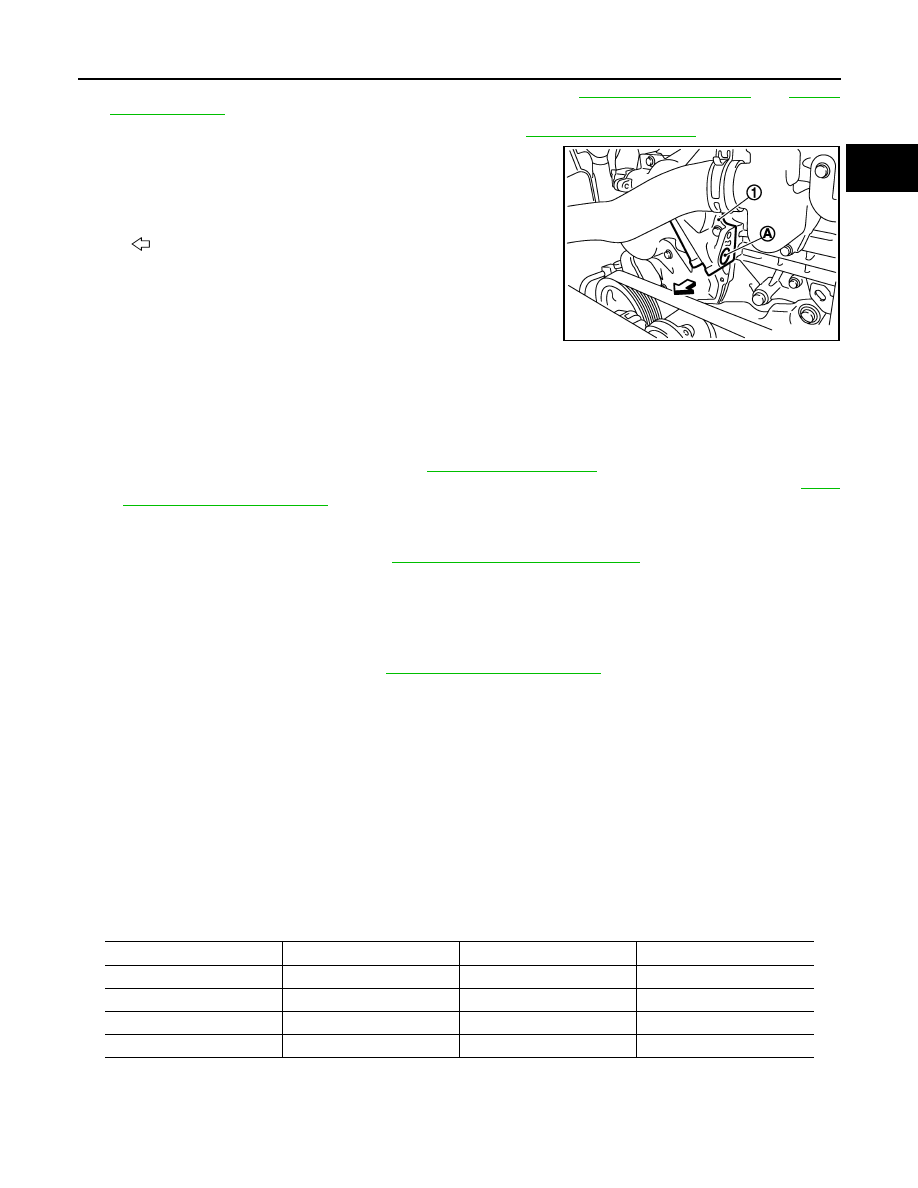
Crank engine, and then check that engine oil comes out from
intake valve timing control solenoid valve hole (A). End crank
after checking.
WARNING:
Be careful not to touch rotating parts. (drive belt, idler pul-
ley, and crankshaft pulley, etc.)
CAUTION:
• Prevent splashing by using a shop cloth so as to prevent
the worker from injury from engine oil and so as to prevent engine oil contamination.
• Prevent splashing by using a shop cloth so as to prevent engine oil from being splashed to
engine and vehicle. Especially, be careful no to apply engine oil to rubber parts of drive belt,
engine mounting insulator, etc. Wipe engine oil off immediately if it is splashed.
5.
Perform the following inspection if engine oil does not come out from intake valve timing control solenoid
valve oil hole of the cylinder head.
• Remove oil filter, and then clean it. Refer to
• Clean oil groove between oil strainer and intake valve timing control solenoid valve. Refer to
6.
Remove components between intake valve timing control solenoid valve and camshaft sprocket (INT),
and then check each oil groove for clogging.
• Clean oil groove if necessary. Refer to
LU-2, "Engine Lubrication System"
7.
After inspection, install removed parts in the reverse order.
Inspection for Leakage
The following are procedures for checking fluids leakage, lubricates leakage.
• Before starting engine, check oil/fluid levels including engine coolant and engine oil. If less than required
quantity, fill to the specified level. Refer to
MA-10, "Fluids and Lubricants"
.
• Use procedure below to check for fuel leakage.
- Turn ignition switch “ON” (with engine stopped). With fuel pressure applied to fuel piping, check for fuel leak-
age at connection points.
- Start engine. With engine speed increased, check again for fuel leakage at connection points.
• Run engine to check for unusual noise and vibration.
NOTE:
If hydraulic pressure inside timing chain tensioner drops after removal/installation, slack in the guide may
generate a pounding noise during and just after engine start. However, this is normal. Noise will stop after
hydraulic pressure rises.
• Warm up engine thoroughly to check there is no leakage of fuel, or any oil/fluids including engine oil and
engine coolant.
• Bleed air from lines and hoses of applicable lines, such as in cooling system.
• After cooling down engine, again check oil/fluid levels including engine oil and engine coolant. Refill to the
specified level, if necessary.
Summary of the inspection items:
*: Transmission/transaxle/CVT fluid, power steering fluid, brake fluid, etc.
1
: Valve timing control cover (bank 1)
: Engine front
JPBIA0410ZZ
Items
Before starting engine
Engine running
After engine stopped
Engine coolant
Level
Leakage
Level
Engine oil
Level
Leakage
Level
Other oils and fluid*
Level
Leakage
Level
Fuel
Leakage
Leakage
Leakage
EM-76
< ON-VEHICLE REPAIR >
OIL SEAL
OIL SEAL
VALVE OIL SEAL
VALVE OIL SEAL : Removal and Installation
INFOID:0000000003139122
REMOVAL
1.
Remove camshaft relating to valve oil seal to be removed. Refer to
2.
Remove valve lifters. Refer to
3.
Turn crankshaft until the cylinder requiring new oil seals is at TDC. This will prevent valve from dropping
into cylinder.
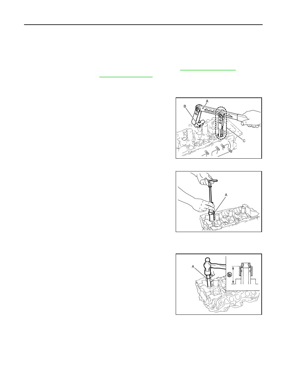
4.
Remove valve collet.
• Compress valve spring with the valve spring compressor [SST:
KV10116200 (J26336-A)] (A), the attachment [SST:
KV10115900 (J26336-20)] (C), the adapter [SST:
KV10109220 (
—
)] (B). Remove valve collet with a magnet
hand.
CAUTION:
When working, take care not to damage valve lifter holes.
5.
Remove valve spring retainer, and valve spring.
6.
Remove valve oil seal using the valve oil seal puller [SST:
KV10107902 (J38959)] (A).
INSTALLATION
1.
Apply new engine oil on new valve oil seal joint and seal lip.
2.
Using the valve oil seal drift [SST: KV10115600 (J38958)] (A),
press fit valve seal to height (b) shown in the figure.
NOTE:
Dimension: Height measured before valve spring seat installa-
tion
3.
Install in the reverse order of removal after this step.
FRONT OIL SEAL
FRONT OIL SEAL : Removal and Installation
INFOID:0000000003139123
REMOVAL
JPBIA0180ZZ
JPBIA0177ZZ
Intake and exhaust
: 14.3 - 14.9 mm (0.563 - 0.587 in)
JPBIA0178ZZ
OIL SEAL
EM-77
< ON-VEHICLE REPAIR >
C
D
E
F
G
H
I
J
K
L
M
A
EM
N
P
O
1.
Remove the following parts:
• Engine undercover with power tool.
• Drive belt: Refer to
• Crankshaft pulley: Refer to
.
2.
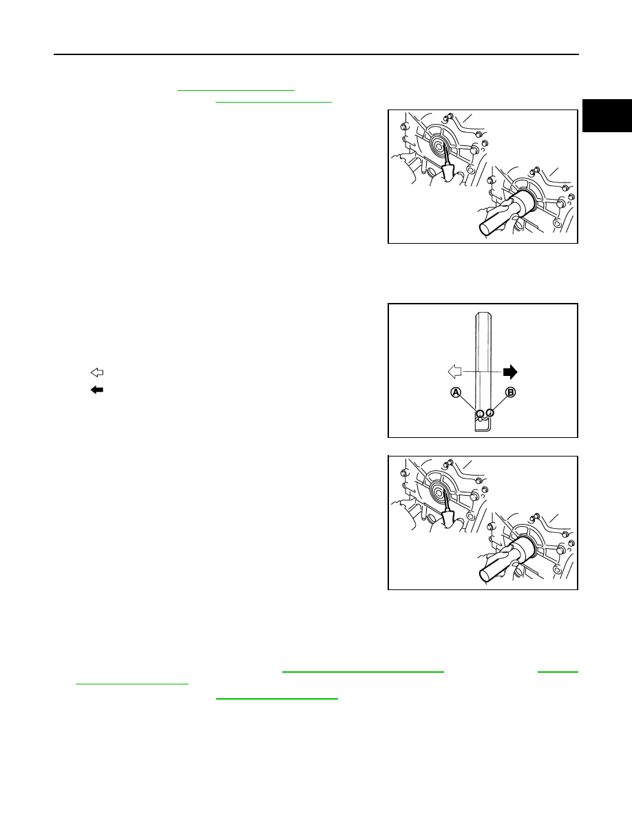
Remove front oil seal using a suitable tool.
CAUTION:
Be careful not to damage front timing chain case and crank-
shaft.
INSTALLATION
1.
Apply new engine oil to both oil seal lip and dust seal lip of new front oil seal.
2.
Install front oil seal.
• Install front oil seal so that each seal lip is oriented as shown in
the figure.
• Using a suitable drift, press-fit until the height of front oil seal is
level with the mounting surface.
- Suitable drift: outer diameter 60 mm (2.36 in), inner diameter
50 mm (1.97 in).
• Check the garter spring is in position and seal lips not inverted
CAUTION:
• Be careful not to damage front timing chain case and
crankshaft.
• Press-fit straight and avoid causing burrs or tilting oil
seal.
3.
Install in the reverse order of removal after this step.
REAR OIL SEAL
REAR OIL SEAL : Removal and Installation
INFOID:0000000003139124
REMOVAL
1.
Remove transmission assembly. Refer to
(2WD models) or
(AWD models).
2.
Remove drive plate. Refer to
.
3.
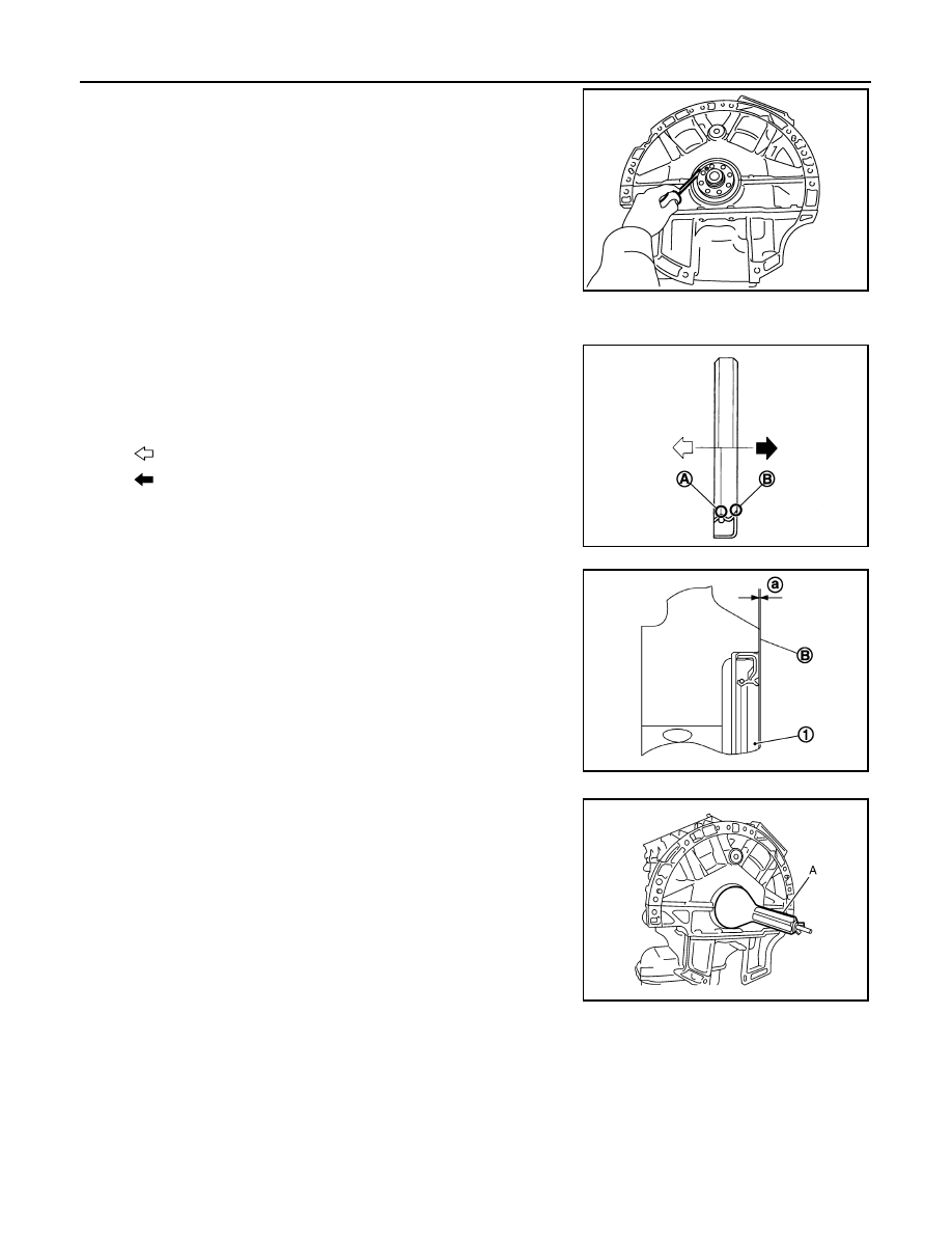
Remove rear oil seal with a suitable tool.
CAUTION:
PBIC2931E
A
: Oil seal lip
B
: Dust seal lip
: Engine inside
: Engine outside
JPBIA0054ZZ
PBIC2931E
EM-78
< ON-VEHICLE REPAIR >
OIL SEAL
Be careful not to damage crankshaft and cylinder block.
INSTALLATION
1.
Install rear oil seal.
• Install rear oil seal so that each seal lip is oriented as shown in
the figure.
• Press in rear oil seal (1) to the position as shown in the figure.
• Using a suitable drift (A), press-fit until the height of rear oil seal is
level with the mounting surface.
- Suitable drift: outer diameter 100 mm (3.94 in), inner diameter 85
mm (3.35 in).
CAUTION:
• Be careful not to damage crankshaft and cylinder block.
• Press-fit straight and avoid causing burrs or tilting oil seal.
2.
Install in the reverse order of removal after this step.
PBIC2932E
A
: Oil seal lip
B
: Dust seal lip
: Engine inside
: Engine outside
JPBIA0054ZZ
B
: Cylinder block rear end face
a
: 0 - 0.5 mm (0 - 0.020 in)
JPBIA0152ZZ
JPBIA0153ZZ
Нет комментариевНе стесняйтесь поделиться с нами вашим ценным мнением.
Текст