Infiniti EX35. Manual — part 900

EVAPORATOR
HA-59
< ON-VEHICLE REPAIR >
C
D
E
F
G
H
J
K
L
M
A
B
HA
N
O
P
EVAPORATOR
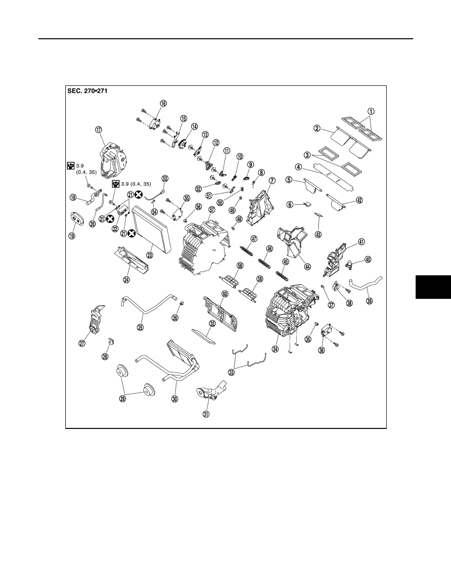
Exploded View
INFOID:0000000003565963
1.
Ventilator seal
2.
Ventilator door
3.
Defroster seal
4.
Packing
5.
Defroster door (right)
6.
Packing
7.
Foot duct (right)
8.
Ventilator door spring
9.
Ventilator door lever
10.
Foot door lever
11.
Foot door link
12. Main link sub
13.
Ventilator door link
14.
Main link
15. Mode door motor bracket
16.
Mode door motor
17.
Evaporator cover
18. Low-pressure pipe 1
19.
Cooler pipe grommet
20.
High-pressure pipe 2
21. O-ring
22.
Expansion valve
23.
Evaporator
24. Insulator
25.
Drain hose
26.
Clamp
27. Evaporator cover adapter
28.
Heater pipe bracket
29.
Heater pipe grommet
30. Heater core
31.
Heater pipe cover
32.
Packing
33. Case packing
34.
Heater & cooling unit case (left)
35.
Air mix door adapter
36. Air mix door motor (driver side)
*
JPIIA0649GB
HA-60
< ON-VEHICLE REPAIR >
EVAPORATOR
Removal and Installation
INFOID:0000000003545496
REMOVAL
1.
Remove low-pressure pipe 1 and high-pressure pipe 2. Refer to
CAUTION:
Cap or wrap the joint of the A/C piping and expansion valve with suitable material such as vinyl
tape to avoid the entry of air.
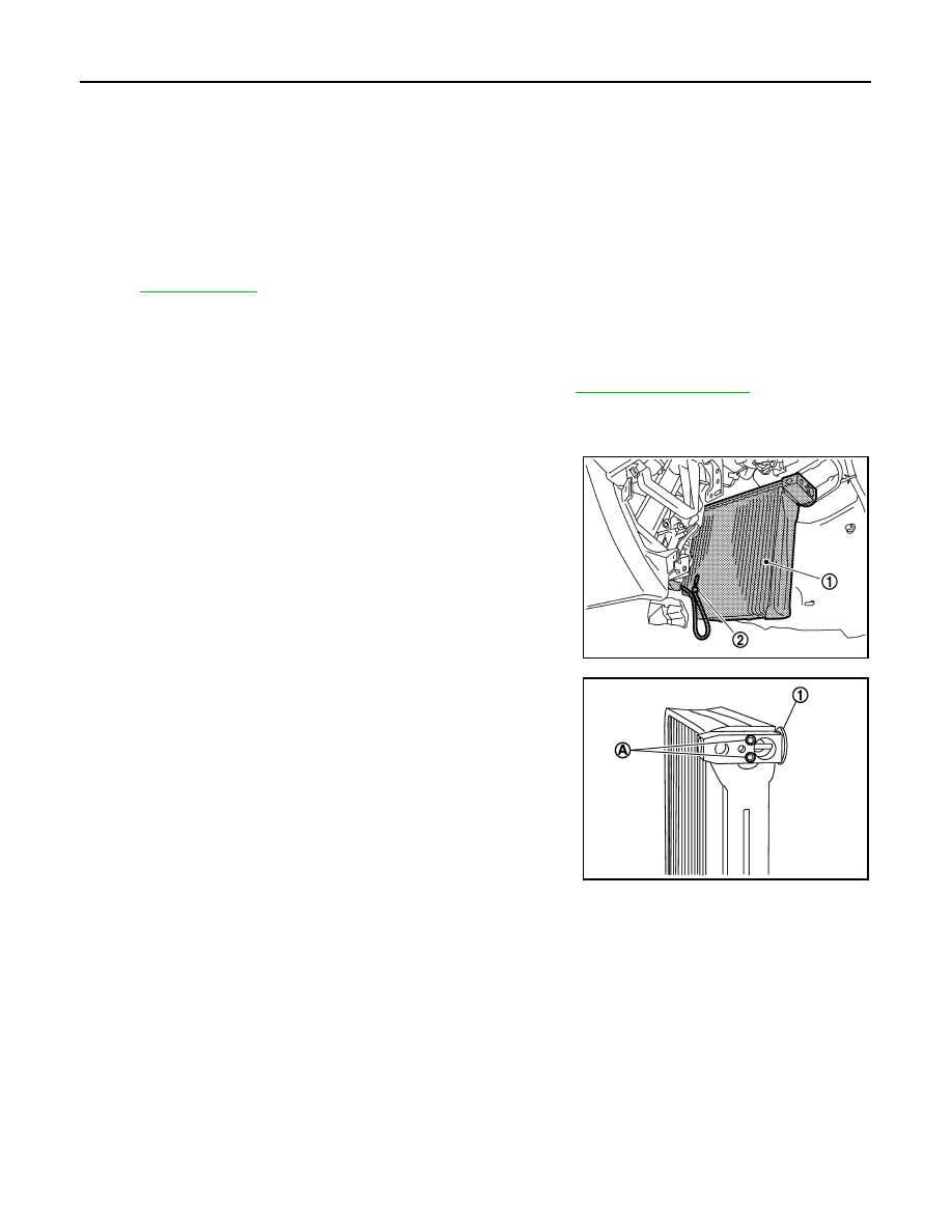
2.
Slide evaporator (1) from heater & cooling unit assembly.
3.
Remove intake sensor (2) from evaporator, and then remove
evaporator.
4.
Remove mounting bolts (A), and then remove expansion valve
(1).
CAUTION:
Cap or wrap the joint of evaporator and expansion valve
with suitable material such as vinyl tape to avoid the entry
of air.
INSTALLATION
Installation is basically the reverse order of removal.
CAUTION:
• Replace O-rings with new ones. Then apply compressor oil to them when installing.
• Female-side piping connection is thin and easy to deform. Slowly insert the male-side piping
straight in axial direction.
• Insert piping securely until a click is heard.
• After piping connection is completed, pull male-side piping by hand to make sure that connection
does not come loose.
• O-rings differ from low-pressure flexible hose (high-pressure pipe 1) and low-pressure pipe 1 (high-
pressure pipe 2).
• Mark the mounting position of intake sensor bracket prior to removal so that the reinstalled sensor
can be located in the same position.
• Check for leakages when recharging refrigerant.
37. J-nut
38.
Front heater duct
39.
Aspirator hose
40. Aspirator
41.
Foot duct (left)
42.
Defroster door (left)
43. Packing
44.
Center case
45.
Foot door (left)
46. Rear ventilator door
47.
Foot door (right)
48.
J-nut
49. Max. cool door lever
50.
Defroster door lever
51.
Defroster door link
52. Max. cool door link
53.
Intake sensor
54.
Intake sensor bracket
55. Air mix door motor (passenger side)
56.
Air mix door adapter
57.
Heater & cooling unit case (right)
58. Max. cool door (right)
59.
Max. cool door (left)
60.
Air mix door (Slide door)
*With left and right ventilation temperature separately system.
for symbols in the figure.
JPIIA0650ZZ
JSIIA0102ZZ
EXPANSION VALVE
HA-61
< ON-VEHICLE REPAIR >
C
D
E
F
G
H
J
K
L
M
A
B
HA
N
O
P
EXPANSION VALVE
Exploded View
INFOID:0000000003565965
1.
Ventilator seal
2.
Ventilator door
3.
Defroster seal
4.
Packing
5.
Defroster door (right)
6.
Packing
7.
Foot duct (right)
8.
Ventilator door spring
9.
Ventilator door lever
10.
Foot door lever
11.
Foot door link
12. Main link sub
13.
Ventilator door link
14.
Main link
15. Mode door motor bracket
16.
Mode door motor
17.
Evaporator cover
18. Low-pressure pipe 1
19.
Cooler pipe grommet
20.
High-pressure pipe 2
21. O-ring
22.
Expansion valve
23.
Evaporator
24. Insulator
25.
Drain hose
26.
Clamp
27. Evaporator cover adapter
28.
Heater pipe bracket
29.
Heater pipe grommet
30. Heater core
31.
Heater pipe cover
32.
Packing
33. Case packing
34.
Heater & cooling unit case (left)
35.
Air mix door adapter
36. Air mix door motor (driver side)
*
JPIIA0649GB
HA-62
< ON-VEHICLE REPAIR >
EXPANSION VALVE
Removal and Installation
INFOID:0000000003545498
REMOVAL
1.
Remove low-pressure pipe 1 and high-pressure pipe 2. Refer to
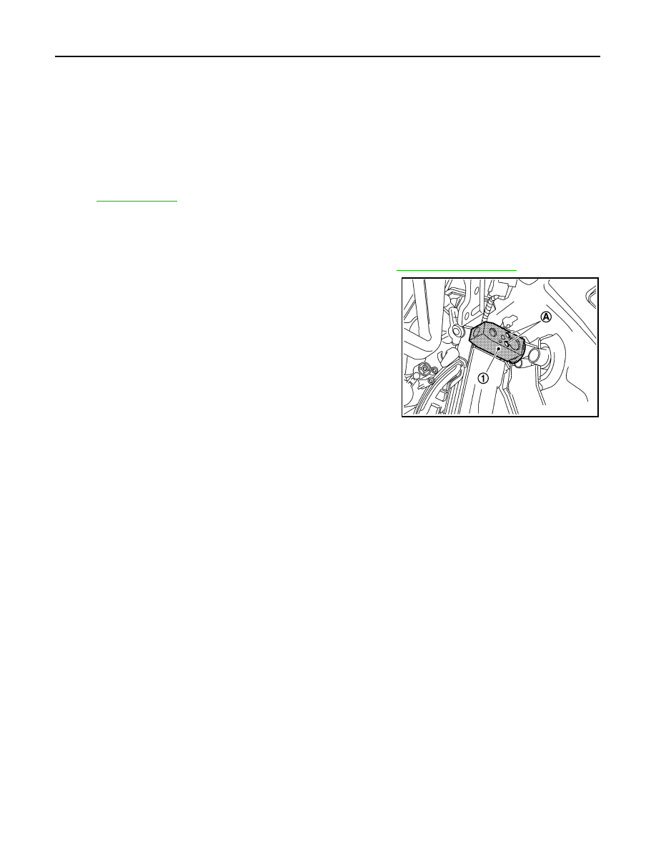
2.
Remove mounting bolts (A), and then remove expansion valve
(1).
CAUTION:
Cap or wrap the joint of evaporator and expansion valve
with suitable material such as vinyl tape to avoid the entry
of air.
INSTALLATION
Installation is basically the reverse order of removal.
CAUTION:
• Replace O-rings with new ones. Then apply compressor oil to them when installing.
• O-rings are different from low-pressure pipe 1 (high-pressure pipe 1) and low-pressure pipe 2 (high-
pressure pipe 2).
• Check for leakages when recharging refrigerant.
37. J-nut
38.
Front heater duct
39.
Aspirator hose
40. Aspirator
41.
Foot duct (left)
42.
Defroster door (left)
43. Packing
44.
Center case
45.
Foot door (left)
46. Rear ventilator door
47.
Foot door (right)
48.
J-nut
49. Max. cool door lever
50.
Defroster door lever
51.
Defroster door link
52. Max. cool door link
53.
Intake sensor
54.
Intake sensor bracket
55. Air mix door motor (passenger side)
56.
Air mix door adapter
57.
Heater & cooling unit case (right)
58. Max. cool door (right)
59.
Max. cool door (left)
60.
Air mix door (Slide door)
*With left and right ventilation temperature separately system.
for symbols in the figure.
JPIIA0710ZZ
Нет комментариевНе стесняйтесь поделиться с нами вашим ценным мнением.
Текст