Infiniti EX35. Manual — part 899
CONDENSER PIPE ASSEMBLY
HA-55
< ON-VEHICLE REPAIR >
C
D
E
F
G
H
J
K
L
M
A
B
HA
N
O
P
CONDENSER PIPE ASSEMBLY
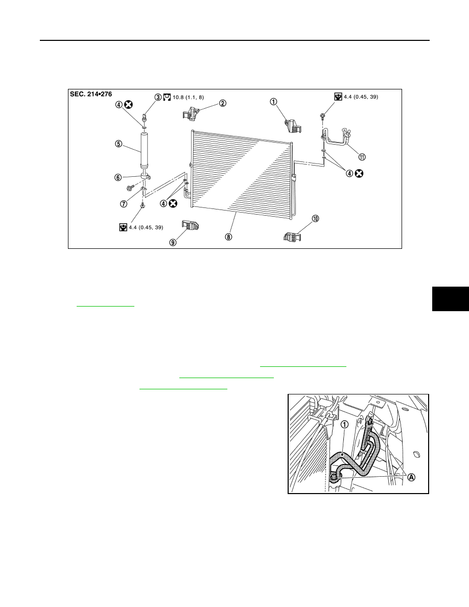
Exploded View
INFOID:0000000003565978
Removal and Installation
INFOID:0000000003545490
REMOVAL
1.
Use a refrigerant collecting equipment (for HFC-134a) to discharge the refrigerant.
2.
Remove air cleaner case (LH) and air duct (LH). Refer to
.
3.
Remove hood lock cover. Refer to
.
4.
Remove horn. Refer to
5.
Remove mounting bolt (A) from condenser pipe assembly (1).
1.
Condenser upper bracket (left)
2.
Condenser upper bracket (right)
3.
Refrigerant pressure sensor
4.
O-ring
5.
Liquid tank
6.
Liquid tank bracket
7.
Bracket
8.
Condenser
9.
Condenser lower bracket (right)
10. Condenser lower bracket (left)
11.
Condenser pipe assembly
Refer to
JPIIA0704GB
JPIIA0705ZZ
HA-56
< ON-VEHICLE REPAIR >
CONDENSER PIPE ASSEMBLY
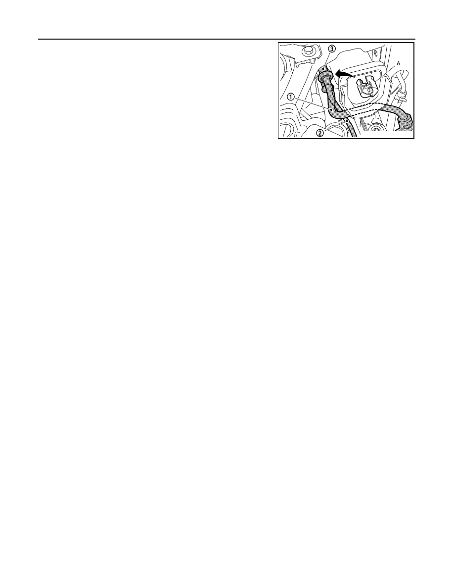
6.
Disconnect one-touch joint between high-pressure flexible hose
(1) and condenser pipe assembly (3) with disconnector (A)
(SST: 9253089912).
CAUTION:
Cap or wrap the joint of the A/C piping with suitable mate-
rial such as vinyl tape to avoid the entry of air.
7.
Disconnect one-touch joints between high-pressure pipe 1 (2)
and condenser pipe assembly with disconnector (A) (SST:
9253089908).
CAUTION:
Cap or wrap the joint of the A/C piping with suitable mate-
rial such as vinyl tape to avoid the entry of air.
INSTALLATION
Installation is basically the reverse order of removal.
CAUTION:
• Replace O-rings with new ones. Then apply compressor oil to them when installing.
• Female-side piping connection is thin and easy to deform. Slowly insert the male-side piping
straight in axial direction.
• Insert piping securely until a click is heard.
• After piping connection is completed, pull male-side piping by hand to make sure that connection
does not come loose.
• Check for leakages when recharging refrigerant.
JPIIA0702ZZ
LIQUID TANK
HA-57
< ON-VEHICLE REPAIR >
C
D
E
F
G
H
J
K
L
M
A
B
HA
N
O
P
LIQUID TANK
Exploded View
INFOID:0000000003565979
Removal and Installation
INFOID:0000000003545492
REMOVAL
1.
Use a refrigerant collecting equipment (for HFC-134a) to discharge the refrigerant.
2.
Remove hood lock cover. Refer to
.
3.
Clean liquid tank and its surrounding area. Then remove dust and rust from liquid tank.
CAUTION:
Be sure to clean carefully.
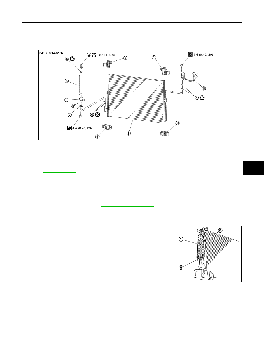
4.
Remove mounting bolts (A) from liquid tank (1).
5.
Remove liquid tank.
CAUTION:
Cap or wrap the joint of the A/C piping and liquid tank with
suitable material such as vinyl tape to avoid the entry of air.
INSTALLATION
Install liquid tank, and then install liquid tank bracket on condenser.
CAUTION:
• Check that liquid tank bracket is securely installed at protrusion of condenser. (Check that liquid
tank bracket does not move to a position below center of liquid tank.)
• Replace O-rings of the A/C piping with new ones. Then apply compressor oil to them when installing.
• Check for leakages when recharging refrigerant.
1.
Condenser upper bracket (left)
2.
Condenser upper bracket (right)
3.
Refrigerant pressure sensor
4.
O-ring
5.
Liquid tank
6.
Liquid tank bracket
7.
Bracket
8.
Condenser
9.
Condenser lower bracket (right)
10. Condenser lower bracket (left)
11.
Condenser pipe assembly
Refer to
JPIIA0704GB
JPIIA0709ZZ
HA-58
< ON-VEHICLE REPAIR >
REFRIGERANT PRESSURE SENSOR
REFRIGERANT PRESSURE SENSOR
Exploded View
INFOID:0000000003565980
Removal and Installation
INFOID:0000000003545494
REMOVAL
1.
Remove liquid tank. Refer to
.
2.
Fix the liquid tank (1) with a vise (A). Remove the refrigerant
pressure sensor (2) with a wrench (B).
CAUTION:
Be careful not to damage liquid tank.
INSTALLATION
Installation is basically the reverse order of removal.
CAUTION:
• Apply compressor oil to O-ring of refrigerant pressure sensor when installing.
• Check for leakages when recharging refrigerant.
1.
Condenser upper bracket (left)
2.
Condenser upper bracket (right)
3.
Refrigerant pressure sensor
4.
O-ring
5.
Liquid tank
6.
Liquid tank bracket
7.
Bracket
8.
Condenser
9.
Condenser lower bracket (right)
10. Condenser lower bracket (left)
11.
Condenser pipe assembly
Refer to
for symbols in the figure.
JPIIA0704GB
JSIIA0075ZZ
Нет комментариевНе стесняйтесь поделиться с нами вашим ценным мнением.
Текст