Infiniti EX35. Manual — part 898
LOW-PRESSURE PIPE 1 AND HIGH-PRESSURE PIPE 2
HA-51
< ON-VEHICLE REPAIR >
C
D
E
F
G
H
J
K
L
M
A
B
HA
N
O
P
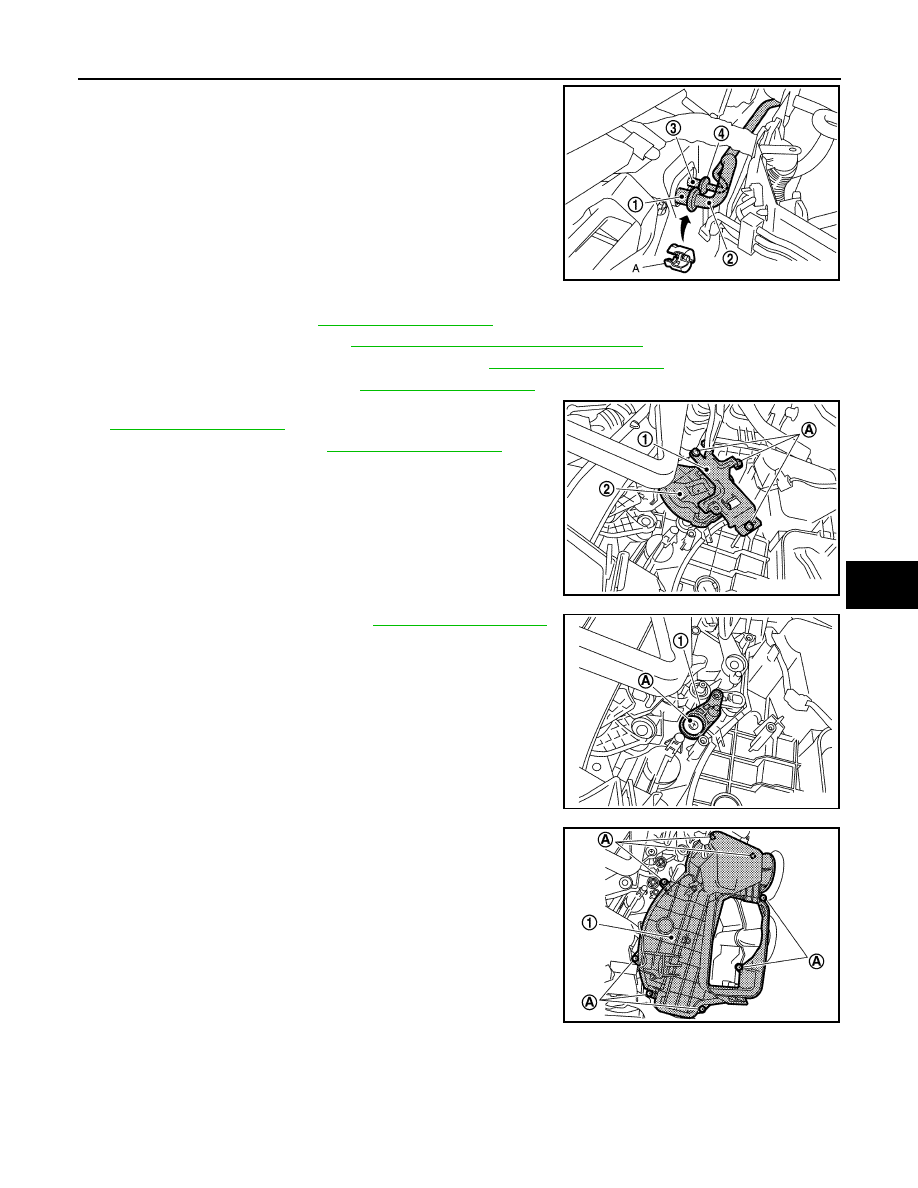
4.
Disconnect one-touch joint between low-pressure pipe 1 (1) and
low-pressure pipe 2 (2) with disconnector (SST: 9253089916)
(A).
CAUTION:
Cap or wrap the joint of the A/C piping with suitable mate-
rial such as vinyl tape to avoid the entry of air.
5.
Disconnect one-touch joints between high-pressure pipe 1 (4)
and high-pressure pipe 2 (3) with disconnector (SST:
9253089908).
CAUTION:
Cap or wrap the joint of the A/C piping with suitable mate-
rial such as vinyl tape to avoid the entry of air.
6.
Remove blower unit. Refer to
7.
Remove foot grille (right). Refer to
VTL-59, "FOOT GRILLE : Exploded View"
8.
Remove air mix door motor (passenger side). Refer to
.
9.
Remove mode door motor. Refer to
.
10. Remove mounting screws (A), and then remove bracket (1).
11. Remove main link (2). Refer to
.
12. Remove max. cool door link. Refer to
.
13. Remove mounting screws (A), and then remove evaporator
cover (1).
JPIIA0657ZZ
JPIIA0694ZZ
JPIIA0695ZZ
JPIIA0696ZZ
HA-52
< ON-VEHICLE REPAIR >
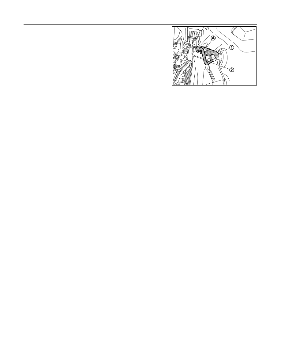
LOW-PRESSURE PIPE 1 AND HIGH-PRESSURE PIPE 2
14. Remove mounting bolt (A), and then remove low-pressure pipe
1 (1) and high-pressure pipe 2 (2).
CAUTION:
Cap or wrap the joint of the A/C piping and expansion valve
with suitable material such as vinyl tape to avoid the entry
of air.
INSTALLATION
Installation is basically the reverse order of removal.
CAUTION:
• Replace O-rings with new ones. Then apply compressor oil to them when installing.
• Female-side piping connection is thin and easy to deform. Slowly insert the male-side piping
straight in axial direction.
• Insert piping securely until a click is heard.
• After piping connection is completed, pull male-side piping by hand to make sure that connection
does not come loose.
• Check for leakages when recharging refrigerant.
JPIIA0697ZZ
CONDENSER
HA-53
< ON-VEHICLE REPAIR >
C
D
E
F
G
H
J
K
L
M
A
B
HA
N
O
P
CONDENSER
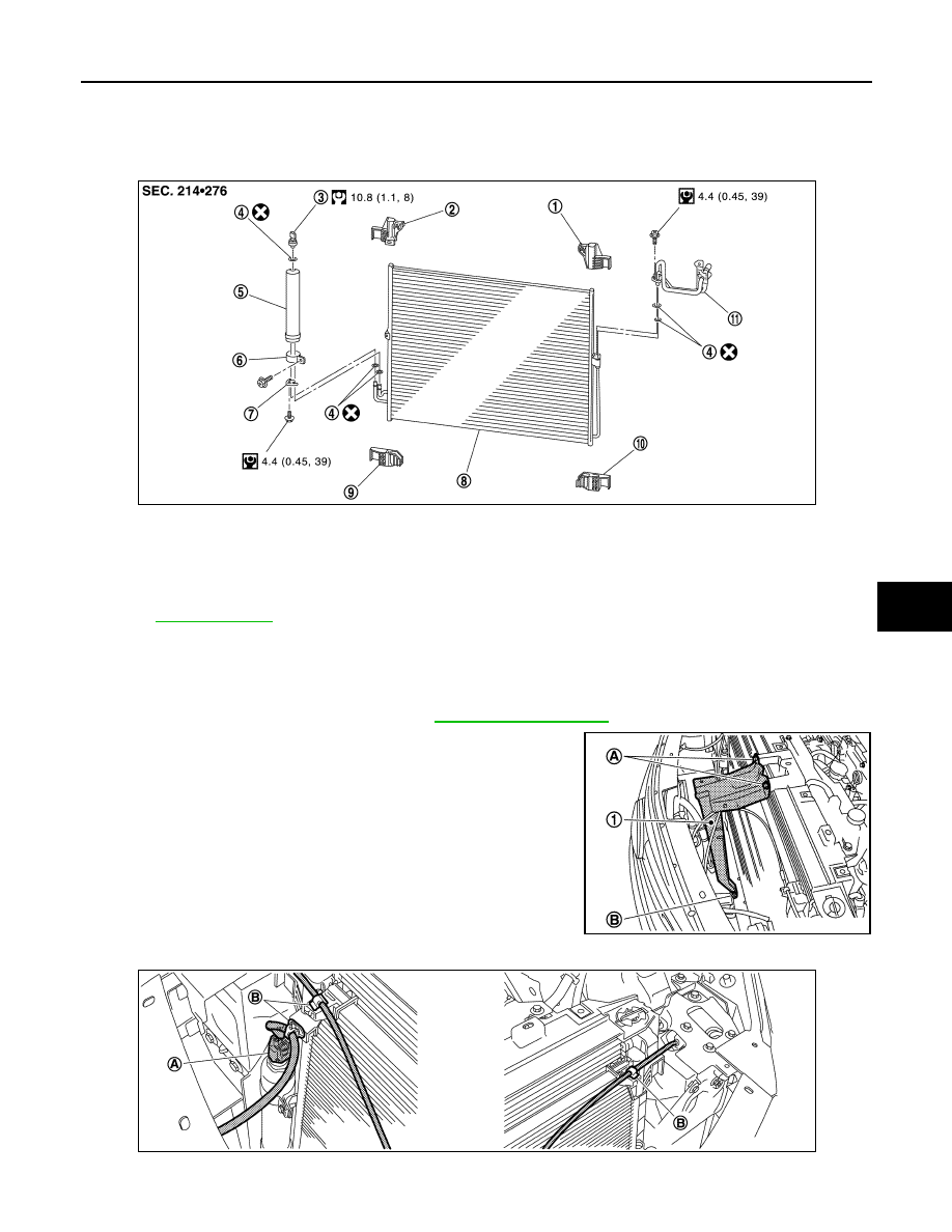
Exploded View
INFOID:0000000003545487
Removal and Installation
INFOID:0000000003545488
REMOVAL
1.
Remove condenser pipe assembly. Refer to
2.
Remove mounting bolts (A) and nut (B), and then remove radia-
tor core support bracket (1).
3.
Disconnect refrigerant pressure sensor connector (A) and harness clips (B).
1.
Condenser upper bracket (left)
2.
Condenser upper bracket (right)
3.
Refrigerant pressure sensor
4.
O-ring
5.
Liquid tank
6.
Liquid tank bracket
7.
Bracket
8.
Condenser
9.
Condenser lower bracket (right)
10. Condenser lower bracket (left)
11.
Condenser pipe assembly
Refer to
JPIIA0704GB
JPIIA0706ZZ
JPIIA0707ZZ
HA-54
< ON-VEHICLE REPAIR >
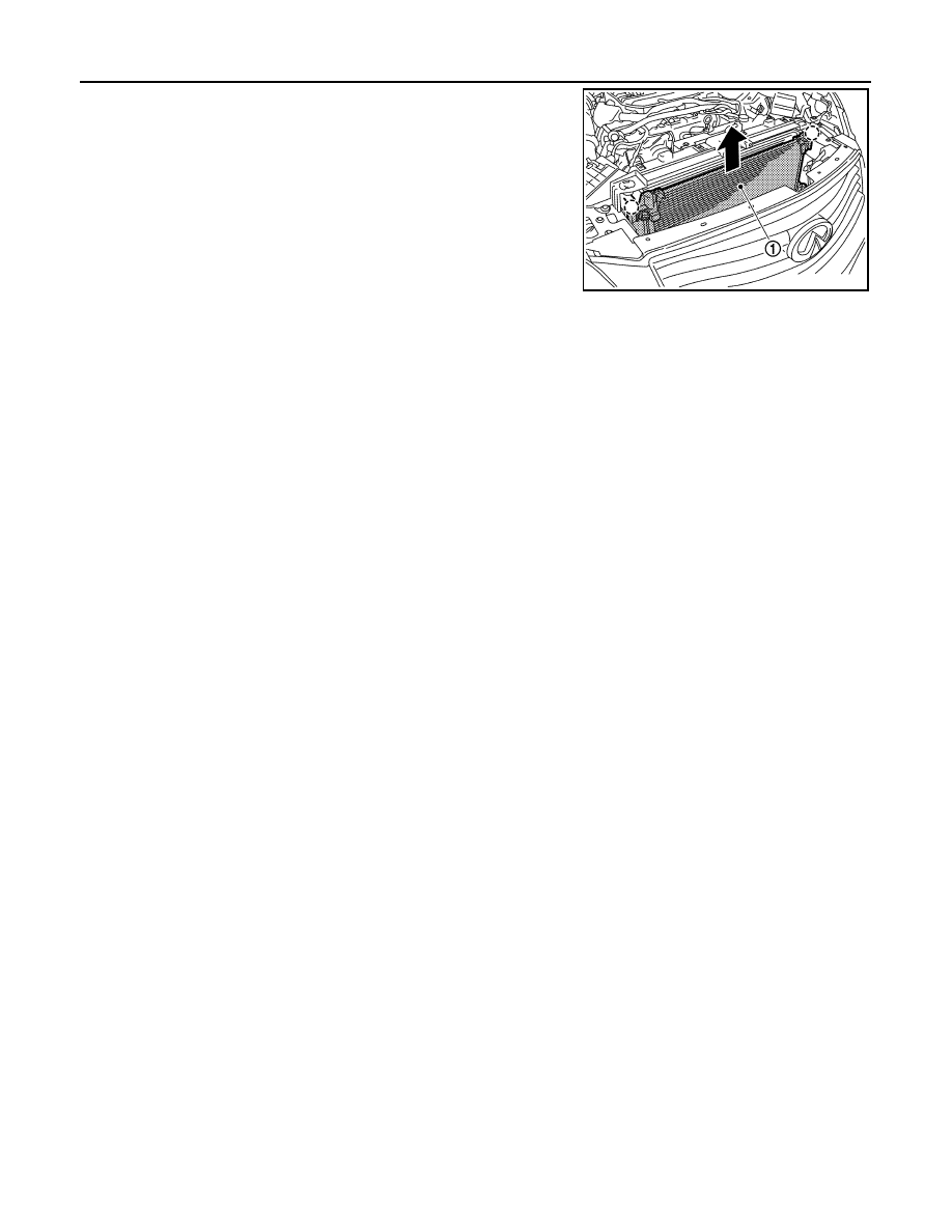
CONDENSER
4.
Pull condenser (1) upward of vehicle, and then remove con-
denser (as shown in the figure).
CAUTION:
Be careful not to damage core surface of condenser.
INSTALLATION
Installation is basically the reverse order of removal.
CAUTION:
• Replace O-rings with new ones. Then apply compressor oil to them when installing.
• Female-side piping connection is thin and easy to deform. Slowly insert the male-side piping
straight in axial direction.
• Insert piping securely until a click is heard.
• After piping connection is completed, pull male-side piping by hand to make sure that connection
does not come loose.
• Check for leakages when recharging refrigerant.
JPIIA0708ZZ
Нет комментариевНе стесняйтесь поделиться с нами вашим ценным мнением.
Текст