Infiniti EX35. Manual — part 1460
TM-228
< DISASSEMBLY AND ASSEMBLY >
[5AT: RE5R05A]
TRANSMISSION ASSEMBLY
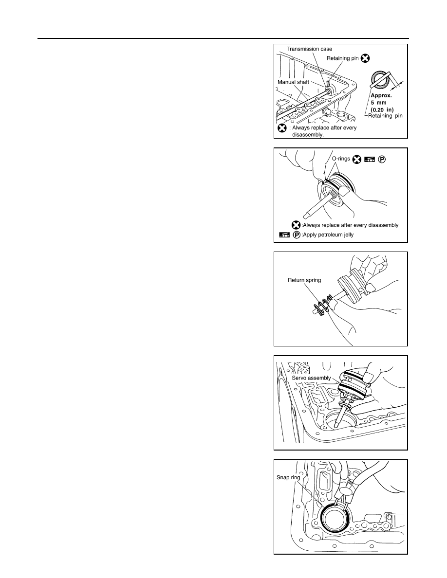
7.
Install retaining pin into the transmission case and manual shaft.
a.
Fit pinhole of the transmission case to pinhole of the manual
shaft with a pin punch.
b.
Use a hammer to tap the retaining pin into the transmission
case.
CAUTION:
Drive retaining pin to 5
±
1 mm (0.20
±
0.04 in) over the trans-
mission case.
8.
Install O-rings to servo assembly.
9.
Install return spring to servo assembly.
10. Install servo assembly in transmission case.
11. Using a pair of snap ring pliers, install snap ring to transmission
case.
SCIA2427E
SCIA5719E
SCIA5717E
SCIA5679E
SCIA2333E
TRANSMISSION ASSEMBLY
TM-229
< DISASSEMBLY AND ASSEMBLY >
[5AT: RE5R05A]
C
E
F
G
H
I
J
K
L
M
A
B
TM
N
O
P
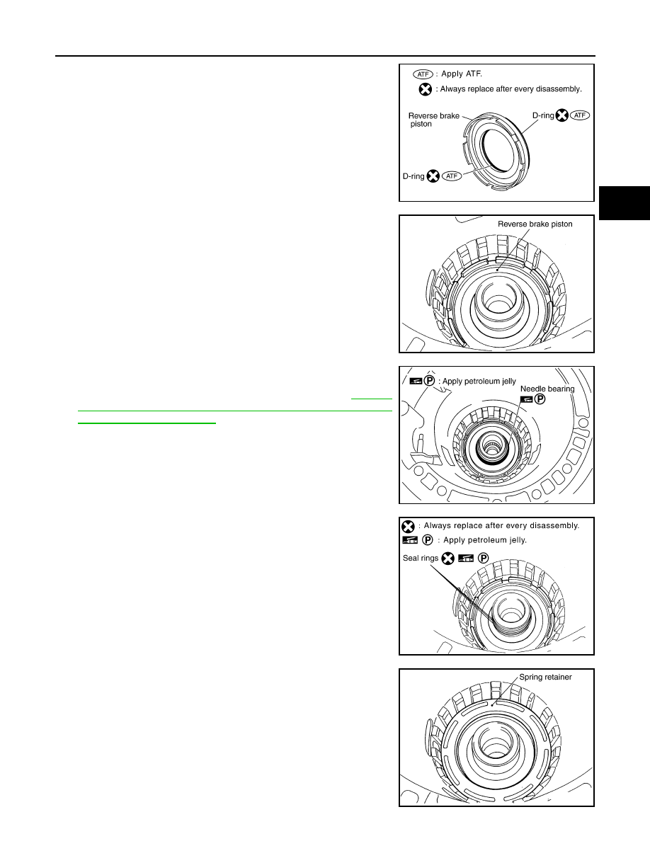
12. Install D-rings in reverse brake piston.
13. Install reverse brake piston in transmission case.
14. Install needle bearing to drum support edge surface.
CAUTION:
Check the direction of needle bearing. Refer to
"Location of Adjusting Shims, Needle Bearings, Thrust
Washers and Snap Rings"
.
15. Install seal rings to drum support.
16. Install spring retainer and return spring in transmission case.
SCIA6330E
SCIA2325E
SCIA2796E
SCIA3333E
SCIA2324E
TM-230
< DISASSEMBLY AND ASSEMBLY >
[5AT: RE5R05A]
TRANSMISSION ASSEMBLY
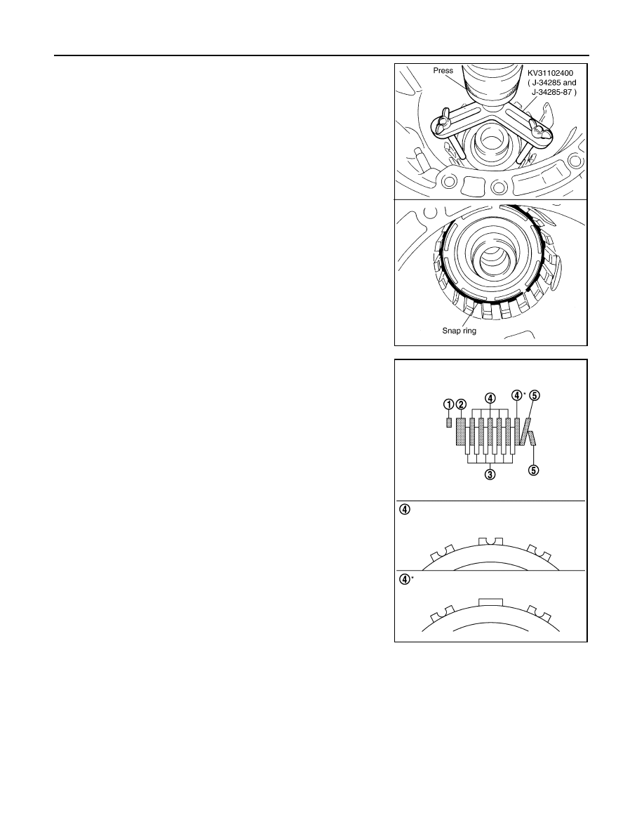
17. Set the SST on spring retainer and install snap ring (fixing spring
retainer) in transmission case while compressing return spring.
CAUTION:
Securely assemble them using a flat-bladed screwdriver so
that snap ring tension is slightly weak.
18. Install reverse brake drive plates, driven plates, dish plates and
retaining plate in transmission case.
CAUTION:
Check order of plates.
SCIA5877E
1
: Snap ring
2
: Retaining plate
3
: Drive plate
4
: Driven plate
5
: Dish plate
6/6
: Drive plate / Driven plate
JPDIA0568ZZ
TRANSMISSION ASSEMBLY
TM-231
< DISASSEMBLY AND ASSEMBLY >
[5AT: RE5R05A]
C
E
F
G
H
I
J
K
L
M
A
B
TM
N
O
P
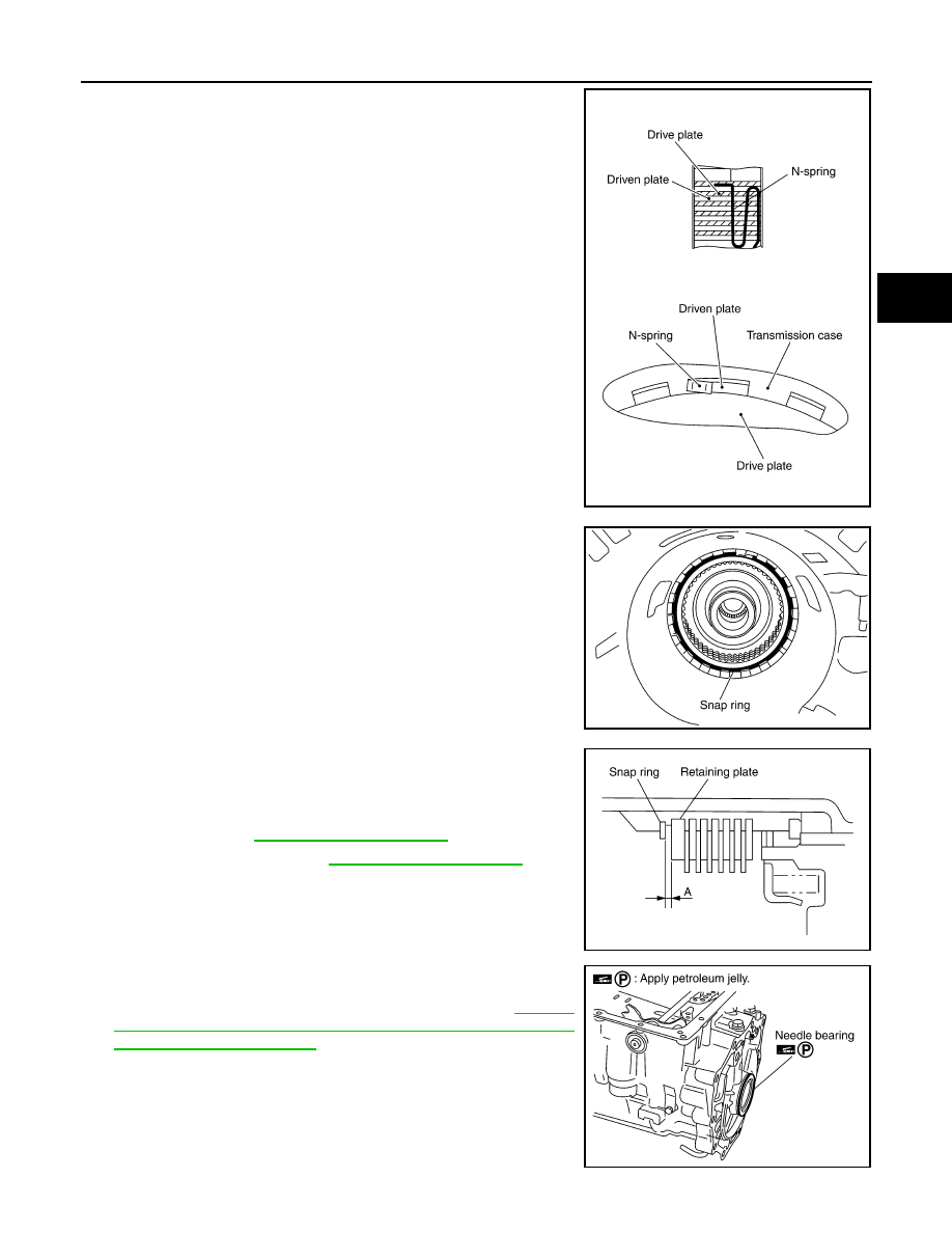
19. Assemble N-spring.
20. Install reverse brake retaining plate in transmission case.
21. Install snap ring in transmission case.
22. Measure clearance between retaining plate and snap ring. If not
within specified clearance, select proper retaining plate.
23. Install needle bearing to transmission case.
CAUTION:
Check the direction of needle bearing. Refer to
"Location of Adjusting Shims, Needle Bearings, Thrust
Washers and Snap Rings"
.
SCIA5249E
SCIA2439E
Specified clearance “A”
Standard:
SCIA3129E
SCIA5031E
Нет комментариевНе стесняйтесь поделиться с нами вашим ценным мнением.
Текст