Infiniti EX35. Manual — part 897
HIGH-PRESSURE PIPE 1
HA-47
< ON-VEHICLE REPAIR >
C
D
E
F
G
H
J
K
L
M
A
B
HA
N
O
P
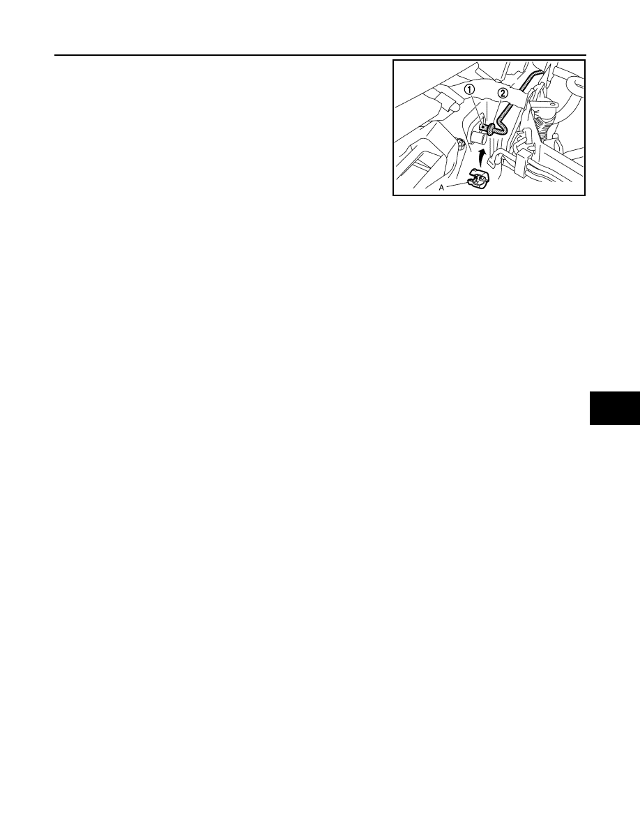
8.
Disconnect one-touch joint between high-pressure pipe 1 (1)
and high-pressure pipe 2 (2) with disconnector (A) (SST:
9253089908).
CAUTION:
Cap or wrap the joint of the A/C piping with suitable mate-
rial such as vinyl tape to avoid the entry of air.
9.
Remove high-pressure pipe 1.
INSTALLATION
Installation is basically the reverse order of removal.
CAUTION:
• Replace O-rings with new ones. Then apply compressor oil to them when installing.
• Female-side piping connection is thin and easy to deform. Slowly insert the male-side piping
straight in axial direction.
• Insert piping securely until a click is heard.
• After piping connection is completed, pull male-side piping by hand to make sure that connection
does not come loose.
• Check for leakages when recharging refrigerant.
JPIIA0703ZZ
HA-48
< ON-VEHICLE REPAIR >
LOW-PRESSURE PIPE 2
LOW-PRESSURE PIPE 2
Exploded View
INFOID:0000000003562730
HA-13, "Refrigerant Connection"
.
Removal and Installation
INFOID:0000000003562731
REMOVAL
1.
Use a refrigerant collecting equipment (for HFC-134a) to discharge the refrigerant.
2.
Remove cowl top cover. Refer to
.
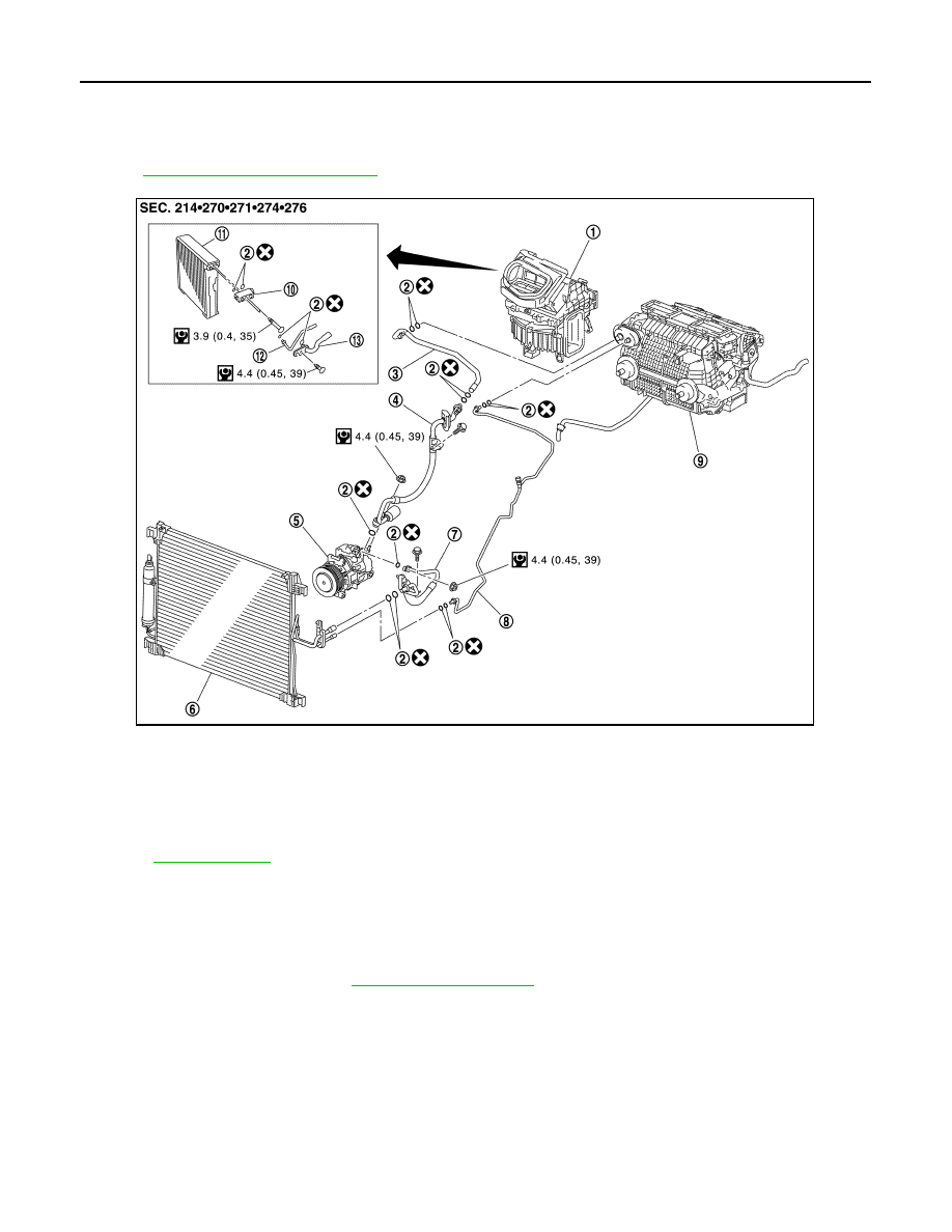
1.
Blower unit
2.
O-ring
3.
Low-pressure pipe 2
4.
Low-pressure flexible hose
5.
Compressor
6.
Condenser
7.
High-pressure flexible hose
8.
High-pressure pipe 1
9.
Heater & cooling unit assembly
10. Expansion valve
11.
Evaporator
12. High-pressure pipe 2
13. Low-pressure pipe 1
Refer to
for symbols in the figure.
JPIIA0684GB

LOW-PRESSURE PIPE 2
HA-49
< ON-VEHICLE REPAIR >
C
D
E
F
G
H
J
K
L
M
A
B
HA
N
O
P
3.
Disconnect one-touch joint between low-pressure flexible hose
(1) and low-pressure pipe 2 (2) with disconnector (A) (SST:
9253089916).
CAUTION:
Cap or wrap the joint of the A/C piping with suitable mate-
rial such as vinyl tape to avoid the entry of air.
4.
Disconnect one-touch joint between low-pressure pipe 1 (1) and
low-pressure pipe 2 (2) with disconnector (A) (SST:
9253089916).
CAUTION:
Cap or wrap the joint of the A/C piping with suitable mate-
rial such as vinyl tape to avoid the entry of air.
5.
Remove low-pressure pipe 2.
INSTALLATION
Installation is basically the reverse order of removal.
CAUTION:
• Replace O-rings with new ones. Then apply compressor oil to them when installing.
• Female-side piping connection is thin and easy to deform. Slowly insert the male-side piping
straight in axial direction.
• Insert piping securely until a click is heard.
• After piping connection is completed, pull male-side piping by hand to make sure that connection
does not come loose.
• Check for leakages when recharging refrigerant.
JPIIA0698ZZ
JPIIA0699ZZ

HA-50
< ON-VEHICLE REPAIR >
LOW-PRESSURE PIPE 1 AND HIGH-PRESSURE PIPE 2
LOW-PRESSURE PIPE 1 AND HIGH-PRESSURE PIPE 2
Exploded View
INFOID:0000000003545485
HA-13, "Refrigerant Connection"
.
Removal and Installation
INFOID:0000000003545486
REMOVAL
1.
Set the temperature at 18
°
C (60
°
F). Then disconnect the battery cable from the negative terminal.
2.
Use a refrigerant collecting equipment (for HFC-134a) to discharge the refrigerant.
3.
Remove cowl top cover. Refer to
.
1.
Blower unit
2.
O-ring
3.
Low-pressure pipe 2
4.
Low-pressure flexible hose
5.
Compressor
6.
Condenser
7.
High-pressure flexible hose
8.
High-pressure pipe 1
9.
Heater & cooling unit assembly
10. Expansion valve
11.
Evaporator
12. High-pressure pipe 2
13. Low-pressure pipe 1
Refer to
for symbols in the figure.
JPIIA0684GB
Нет комментариевНе стесняйтесь поделиться с нами вашим ценным мнением.
Текст