Infiniti EX35. Manual — part 1085
MWI-18
< FUNCTION DIAGNOSIS >
METER SYSTEM
ENGINE COOLANT TEMPERATURE GAUGE : Component Description
INFOID:0000000003140152
FUEL GAUGE
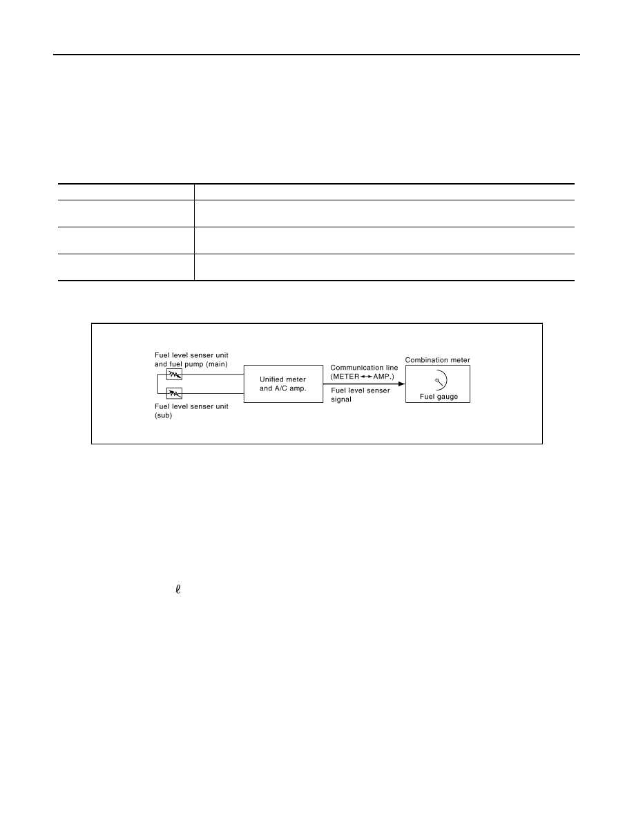
FUEL GAUGE : System Diagram
INFOID:0000000003140153
FUEL GAUGE : System Description
INFOID:0000000003140154
CONTROL OUTLINE
• The unified meter and A/C amp. reads the fuel level sensor signal from the fuel gauge unit and transmits it to
the combination meter with the communication line.
• The combination meter indicates the fuel level on the fuel gauge according to the received fuel level sensor
signal.
REFUEL CONTROL
The unit judges that the driver is refueling the vehicle and accelerates the fuel gauge needle movement if the
fuel level changes by 15 (4 US gal, 3-3/10 Imp gal) or more.
7.
ABS actuator and electric unit (con-
trol unit)
8.
Unified meter and A/C amp.
9.
Combination meter
10. Fuel level sensor unit (sub)
A.
Rear seat (inside right)
B.
Dash side finisher (passenger side)
C.
Hoodledge cover (RH)
D.
2WD [oil pan (upper) RH side]
E.
AWD (oil filter bracket part)
F.
Condenser (front)
G.
Hoodledge cover (LH)
H.
Behind cluster lid C
I.
Rear seat (inside left)
Unit
Description
Combination meter
Indicates the water temperature gauge according to the engine coolant temperature signal re-
ceived from the unified meter and A/C amp. by means of communication line.
Unified meter and A/C amp.
Transmits the engine coolant temperature signal received from ECM with CAN communication
line to the combination meter by means of communication line.
ECM
Transmits the engine coolant temperature signal to the unified meter and A/C amp. with CAN
communication line.
JSNIA0534GB

MWI
METER SYSTEM
MWI-19
< FUNCTION DIAGNOSIS >
C
D
E
F
G
H
I
J
K
L
M
B
A
O
P
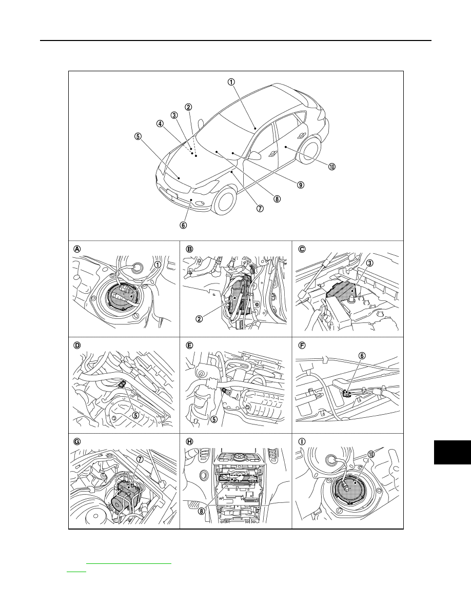
FUEL GAUGE : Component Parts Location
INFOID:0000000003733000
1.
Fuel level sensor unit and fuel pump
(main)
2.
BCM
3.
IPDM E/R
4.
ECM :
5.
Oil pressure switch
6.
Ambient sensor
JPNIA0868ZZ
MWI-20
< FUNCTION DIAGNOSIS >
METER SYSTEM
FUEL GAUGE : Component Description
INFOID:0000000003140156
ODO/TRIP METER
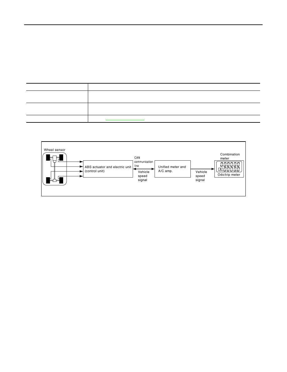
ODO/TRIP METER : System Diagram
INFOID:0000000003140157
ODO/TRIP METER : System Description
INFOID:0000000003140158
• The unified meter and A/C amp. transmits the vehicle speed signal from ABS actuator and electric unit (con-
trol unit) to the combination meter.
• The combination meter calculates the vehicle distance according to the vehicle speed signal. The vehicle
distance is displayed.
7.
ABS actuator and electric unit (con-
trol unit)
8.
Unified meter and A/C amp.
9.
Combination meter
10. Fuel level sensor unit (sub)
A.
Rear seat (inside right)
B.
Dash side finisher (passenger side)
C.
Hoodledge cover (RH)
D.
2WD [oil pan (upper) RH side]
E.
AWD (oil filter bracket part)
F.
Condenser (front)
G.
Hoodledge cover (LH)
H.
Behind cluster lid C
I.
Rear seat (inside left)
Unit
Description
Combination meter
Indicates the fuel gauge according to the fuel level sensor signal received from the unified meter
and A/C amp. by means of communication line.
Unified meter and A/C amp.
Transmits the fuel level sensor signal from the fuel level sensor unit to the combination meter by
means of communication line.
Fuel level sensor unit
.
JSNIA0022GB
MWI
METER SYSTEM
MWI-21
< FUNCTION DIAGNOSIS >
C
D
E
F
G
H
I
J
K
L
M
B
A
O
P
ODO/TRIP METER : Component Parts Location
INFOID:0000000003733002
1.
Fuel level sensor unit and fuel pump
(main)
2.
BCM
3.
IPDM E/R
4.
ECM :
5.
Oil pressure switch
6.
Ambient sensor
JPNIA0868ZZ
Нет комментариевНе стесняйтесь поделиться с нами вашим ценным мнением.
Текст