Infiniti EX35. Manual — part 859
SERVICE DATA AND SPECIFICATIONS (SDS)
FSU-21
< SERVICE DATA AND SPECIFICATIONS (SDS)
[2WD]
C
D
F
G
H
I
J
K
L
M
A
B
FSU
N
O
P
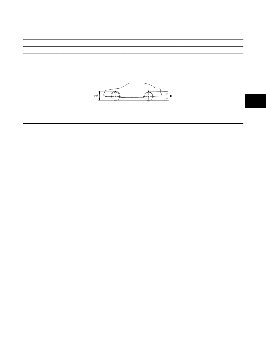
Wheel Height
INFOID:0000000003129924
Measure value under unladen* conditions
*: Fuel, engine coolant and lubricant are full. Spare tire, jack, hand tools and mats are in designated positions.
Applied model
Without 4WAS
With 4WAS
Tire size
225/60R17
225/55R18
Front (Hf)
745 mm (29.33 in)
750 mm (29.53 in)
SFA818A
FSU-22
< SYMPTOM DIAGNOSIS >
[AWD]
NOISE, VIBRATION AND HARSHNESS (NVH) TROUBLESHOOTING
SYMPTOM DIAGNOSIS
NOISE, VIBRATION AND HARSHNESS (NVH) TROUBLESHOOTING
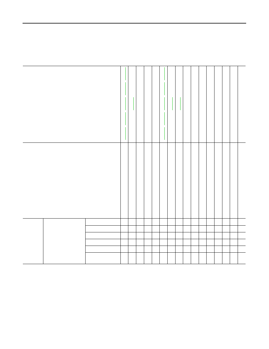
NVH Troubleshooting Chart
INFOID:0000000003129925
Use chart below to help you find the cause of the symptom. If necessary, repair or replace these parts.
×
: Applicable
Reference page
,
,
,
,
—
—
—
,
,
,
,
NVH in
D
L
N section.
NVH in RFD
section.
NVH in F
A
X and
FSU sections.
NVH in WT
section.
NVH in WT
section.
NVH in F
AX section.
NVH in BR
section.
NVH in S
T
section.
Possible cause and SUSPECTED PARTS
Im
p
rop
er i
n
s
tal
la
tio
n
,
loo
s
ene
s
s
S
trut
de
fo
rma
tio
n,
da
ma
ge
or
de
fle
c
ti
on
B
u
s
h
in
g
or m
o
u
n
ting
d
e
te
rio
rati
o
n
P
a
rt
s interference
S
p
ri
ng
fat
ig
u
e
S
us
pe
ns
ion
lo
os
en
es
s
In
co
rrec
t wh
ee
l a
lig
nm
en
t
S
tab
iliz
er b
a
r f
a
ti
gu
e
PR
OP
EL
LE
R
S
H
A
F
T
DIFFERENTIAL
F
R
ONT
AXLE AND FRONT S
U
SPENSION
TI
RE
ROAD
WHEEL
DRIV
E SHAFT
BR
AK
E
S
T
EERING
Symptom
FRONT SUSPENSION
Noise
×
×
×
×
×
×
×
×
×
×
×
×
×
×
Shake
×
×
×
×
×
×
×
×
×
×
×
×
Vibration
×
×
×
×
×
×
×
×
×
×
Shimmy
×
×
×
×
×
×
×
×
×
×
Judder
×
×
×
×
×
×
×
×
Poor quality ride or
handling
×
×
×
×
×
×
×
×
×
×
PRECAUTIONS
FSU-23
< PRECAUTION >
[AWD]
C
D
F
G
H
I
J
K
L
M
A
B
FSU
N
O
P
PRECAUTION
PRECAUTIONS
Precaution for Supplemental Restraint System (SRS) "AIR BAG" and "SEAT BELT
PRE-TENSIONER"
INFOID:0000000003737111
The Supplemental Restraint System such as “AIR BAG” and “SEAT BELT PRE-TENSIONER”, used along
with a front seat belt, helps to reduce the risk or severity of injury to the driver and front passenger for certain
types of collision. This system includes seat belt switch inputs and dual stage front air bag modules. The SRS
system uses the seat belt switches to determine the front air bag deployment, and may only deploy one front
air bag, depending on the severity of a collision and whether the front occupants are belted or unbelted.
Information necessary to service the system safely is included in the “SRS AIRBAG” and “SEAT BELT” of this
Service Manual.
WARNING:
• To avoid rendering the SRS inoperative, which could increase the risk of personal injury or death in
the event of a collision which would result in air bag inflation, all maintenance must be performed by
an authorized NISSAN/INFINITI dealer.
• Improper maintenance, including incorrect removal and installation of the SRS, can lead to personal
injury caused by unintentional activation of the system. For removal of Spiral Cable and Air Bag
Module, see the “SRS AIRBAG”.
• Do not use electrical test equipment on any circuit related to the SRS unless instructed to in this
Service Manual. SRS wiring harnesses can be identified by yellow and/or orange harnesses or har-
ness connectors.
Precaution Necessary for Steering Wheel Rotation after Battery Disconnect
INFOID:0000000003737113
NOTE:
• Before removing and installing any control units, first turn the push-button ignition switch to the LOCK posi-
tion, then disconnect both battery cables.
• After finishing work, confirm that all control unit connectors are connected properly, then re-connect both
battery cables.
• Always use CONSULT-III to perform self-diagnosis as a part of each function inspection after finishing work.
If a DTC is detected, perform trouble diagnosis according to self-diagnosis results.
This vehicle is equipped with a push-button ignition switch and a steering lock unit.
If the battery is disconnected or discharged, the steering wheel will lock and cannot be turned.
If turning the steering wheel is required with the battery disconnected or discharged, follow the procedure
below before starting the repair operation.
OPERATION PROCEDURE
1.
Connect both battery cables.
NOTE:
Supply power using jumper cables if battery is discharged.
2.
Turn the push-button ignition switch to ACC position.
(At this time, the steering lock will be released.)
3.
Disconnect both battery cables. The steering lock will remain released with both battery cables discon-
nected and the steering wheel can be turned.
4.
Perform the necessary repair operation.
5.
When the repair work is completed, re-connect both battery cables. With the brake pedal released, turn
the push-button ignition switch from ACC position to ON position, then to LOCK position. (The steering
wheel will lock when the push-button ignition switch is turned to LOCK position.)
6.
Perform self-diagnosis check of all control units using CONSULT-III.
FSU-24
< PRECAUTION >
[AWD]
PRECAUTIONS
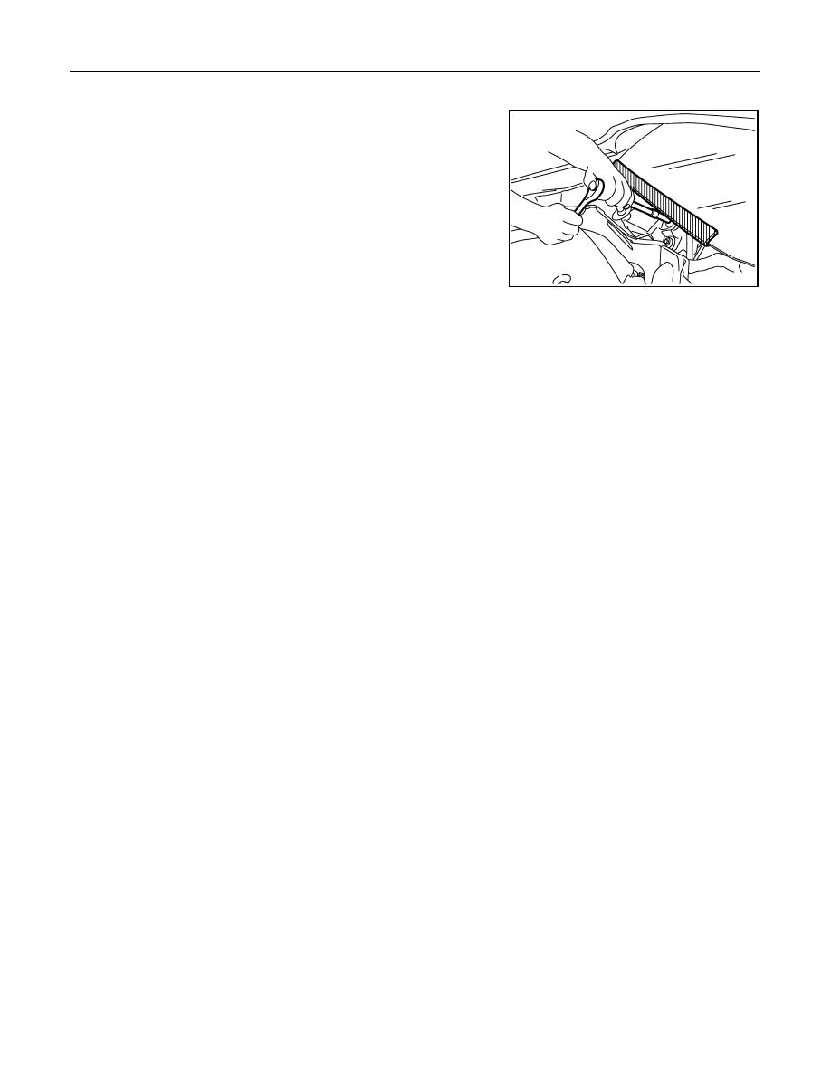
Precaution for Procedure without Cowl Top Cover
INFOID:0000000003737115
When performing the procedure after removing cowl top cover, cover
the lower end of windshield with urethane, etc.
Precautions for Suspension
INFOID:0000000003129929
CAUTION:
• When installing rubber bushings, the final tightening must be carried out under unladen conditions
with tires on ground. Oil might shorten the life of rubber bushings. Be sure to wipe off any spilled oil.
- Unladen conditions mean that fuel, engine coolant and lubricant are full. Spare tire, jack, hand tools
and mats are in designated positions.
• After servicing suspension parts, be sure to check wheel alignment.
• Self-lock nuts are not reusable. Always use new ones when installing. Since new self-lock nuts are
pre-oiled, tighten as they are.
PIIB3706J
Нет комментариевНе стесняйтесь поделиться с нами вашим ценным мнением.
Текст