Infiniti EX35. Manual — part 1451
TM-192
< REMOVAL AND INSTALLATION >
[5AT: RE5R05A]
TRANSMISSION ASSEMBLY
REMOVAL AND INSTALLATION
TRANSMISSION ASSEMBLY
2WD
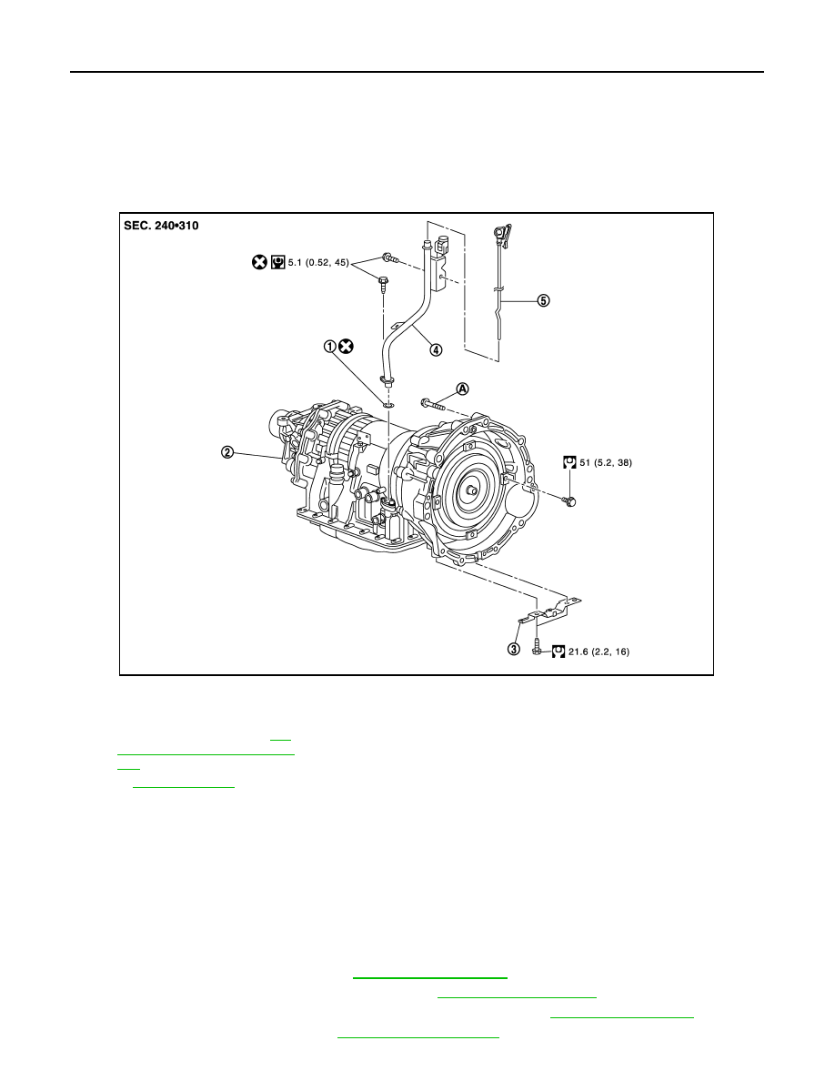
2WD : Exploded View
INFOID:0000000003130639
2WD : Removal and Installation
INFOID:0000000003130640
REMOVAL
CAUTION:
• When removing the A/T assembly from engine, first remove the crankshaft position sensor (POS)
from the A/T assembly.
• Be careful not to damage sensor edge.
1.
Disconnect the battery cable from the negative terminal.
2.
Remove A/T fluid level gauge.
3.
Remove air cleaner case (RH). Refer to
4.
Remove engine lower cover with power tool. Refer to
.
5.
Remove exhaust front tube and center muffler with power tool. Refer to
.
6.
Remove rear propeller shaft. Refer to
1.
O-ring
2.
A/T assembly
3.
Bracket
4.
A/T fluid charging pipe
5.
A/T fluid level gauge
A.
For tightening torque, refer to
192, "2WD : Removal and Installa-
tion"
.
Refer to
for symbols in the figure.
JPDIA0650GB
TRANSMISSION ASSEMBLY
TM-193
< REMOVAL AND INSTALLATION >
[5AT: RE5R05A]
C
E
F
G
H
I
J
K
L
M
A
B
TM
N
O
P
7.
Remove suspension member stay. Refer to
.
8.
Remove exhaust mounting bracket. Refer to
9.
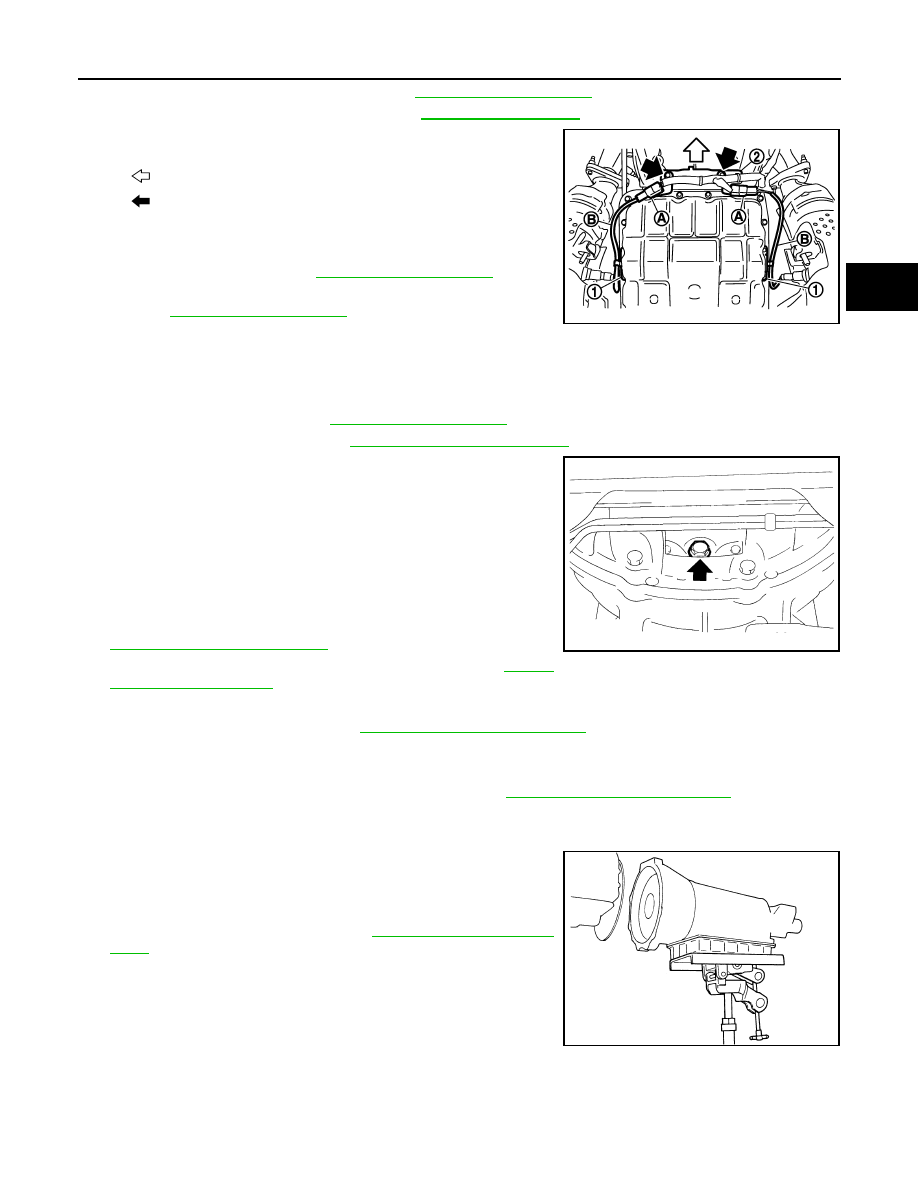
Disconnect heated oxygen sensor 2 harness connectors (A).
10. Remove heated oxygen sensor 2 harness (B) from clips (1).
11. Remove bracket (2) from transmission assembly.
12. Remove control rod. Refer to
.
13. Remove crankshaft position sensor (POS) from A/T assembly.
.
CAUTION:
• Do not subject it to impact by dropping or hitting it.
• Do not disassemble.
• Do not allow metal filings, etc. to get on the sensor's front edge magnetic area.
• Do not place in an area affected by magnetism.
14. Remove starter motor. Refer to
.
15. Remove rear plate cover. Refer to
.
16. Turn crankshaft, and remove the four tightening bolts for drive
plate and torque converter.
CAUTION:
When turning the crankshaft, turn it clockwise as viewed
from the front of the engine.
17. Support A/T assembly with a transmission jack.
CAUTION:
When setting the transmission jack, be careful not to allow
it to collide against the drain plug.
18. Remove rear engine mounting member with power tool. Refer to
19. Remove engine mounting insulator (rear). Refer to
20. Disconnect A/T assembly harness connector and harness clips.
21. Remove air breather hose. Refer to
22. Remove A/T fluid charging pipe from A/T assembly.
23. Remove O-ring from A/T fluid charging pipe.
24. Disconnect fluid cooler tube from A/T assembly. Refer to
.
25. Plug up openings such as the A/T fluid charging pipe hole, etc.
26. Remove bolts fixing A/T assembly to engine assembly with power tool.
27. Remove A/T assembly from vehicle.
CAUTION:
• Secure torque converter to prevent it from dropping.
• Secure A/T assembly to a transmission jack.
28. Remove dynamic damper. Refer to
.
INSTALLATION
Note the following, and Install in the reverse order of removal.
: Vehicle front
: Bolt
SCIA8269E
JPDIA0044ZZ
SCIA0499E
TM-194
< REMOVAL AND INSTALLATION >
[5AT: RE5R05A]
TRANSMISSION ASSEMBLY
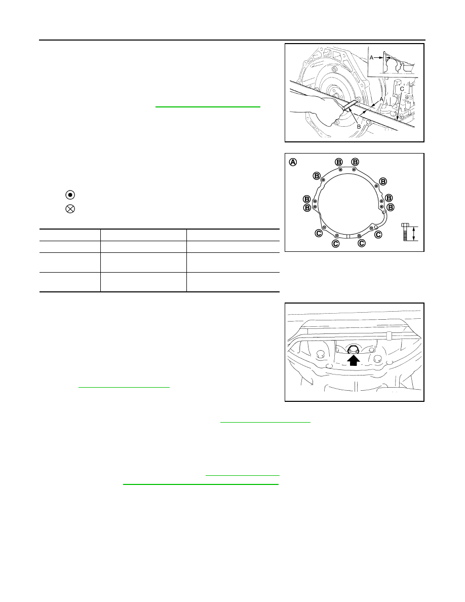
• When installing A/T assembly to the engine assembly, be sure to
check distance (A) to ensure it is within the reference value limit.
• When installing A/T assembly to the engine assembly, attach the
fixing bolts in accordance with the following standard.
• Align the positions of tightening bolts for drive plate with those of
the torque converter, and temporarily tighten the bolts. Then,
tighten the bolts with the specified torque.
CAUTION:
• When turning crankshaft, turn it clockwise as viewed from the
front of the engine.
• When tightening the tightening bolts for the torque converter
after fixing the crankshaft pulley bolts, be sure to confirm the
tightening torque of the crankshaft pulley mounting bolts.
Refer to
.
• Rotate crankshaft several turns and check to be sure that A/T
rotates freely without binding after converter is installed to
drive plate.
• Install crankshaft position sensor (POS). Refer to
2WD : Inspection
INFOID:0000000003130641
INSPECTION AFTER INSTALLATION
Check the following item after completing installation.
• A/T fluid leakage and A/T fluid level. Refer to
• A/T position. Refer to
TM-153, "2WD : Inspection and Adjustment"
AWD
B
: Scale
C
: Straightedge
Distance (A)
: Refer to
JPDIA0042ZZ
A
: View from vehicle front
: Transmission to engine
: Engine to transmission
Bolt symbol
B
C
Number of bolts
8
4
Bolt length
mm (in)
65 (2.56)
35 (1.38)
Tightening torque
N·m (kg-m, ft-lb)
75 (7.7, 55)
46.6 (4.8, 34)
JPDIA0043ZZ
JPDIA0044ZZ
TRANSMISSION ASSEMBLY
TM-195
< REMOVAL AND INSTALLATION >
[5AT: RE5R05A]
C
E
F
G
H
I
J
K
L
M
A
B
TM
N
O
P
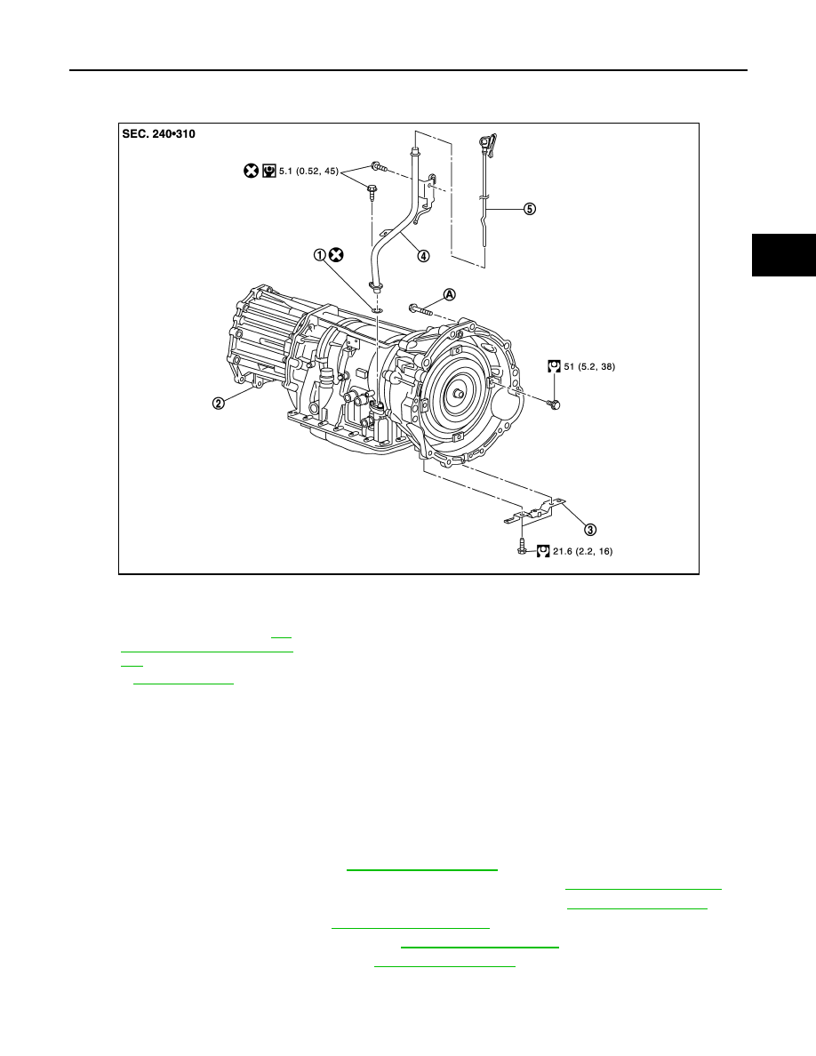
AWD : Exploded View
INFOID:0000000003130642
AWD : Removal and Installation
INFOID:0000000003130643
REMOVAL
CAUTION:
• When removing the A/T assembly from engine, first remove the crankshaft position sensor (POS)
from the A/T assembly.
• Be careful not to damage sensor edge.
1.
Disconnect the battery cable from the negative terminal.
2.
Remove A/T fluid level gauge.
3.
Remove air cleaner case (RH). Refer to
4.
Remove engine lower cover and front under cover with power tool. Refer to
5.
Remove exhaust front tube and center muffler and with power tool. Refer to
6.
Remove rear propeller shaft. Refer to
7.
Remove front cross bar with power tool. Refer to
8.
Remove exhaust mounting bracket. Refer to
1.
O-ring
2.
A/T assembly
3.
Bracket
4.
A/T fluid charging pipe
5.
A/T fluid level gauge
A.
For tightening torque, Refer to
192, "2WD : Removal and Installa-
tion"
Refer to
for symbols in the figure.
JPDIA0718GB
Нет комментариевНе стесняйтесь поделиться с нами вашим ценным мнением.
Текст