Infiniti EX35. Manual — part 1450

TM-188
< ON-VEHICLE REPAIR >
[5AT: RE5R05A]
A/T FLUID COOLER TUBE
A/T FLUID COOLER TUBE
2WD
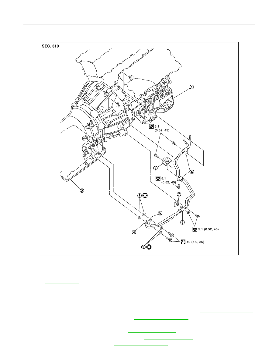
2WD : Exploded View
INFOID:0000000003130633
2WD : Removal and Installation
INFOID:0000000003130634
REMOVAL
1.
Remove the engine lower cover with power tool. Refer to
2.
Remove the exhaust mounting bracket. Refer to
.
3.
Remove the suspension member stay. Refer to
1.
Engine assembly
2.
A/T assembly
3.
Copper washer
4.
A/T fluid cooler tube
5.
A/T fluid cooler tube
6.
Bracket
7.
Clip
Refer to
for symbols in the figure.
JPDIA0554GB
A/T FLUID COOLER TUBE
TM-189
< ON-VEHICLE REPAIR >
[5AT: RE5R05A]
C
E
F
G
H
I
J
K
L
M
A
B
TM
N
O
P
4.
Pull out the A/T fluid cooler hose from the A/T fluid cooler tube. Refer to
5.
Remove the A/T fluid cooler tube from the A/T assembly and engine assembly.
6.
Remove the stabilizer bar. Refer to
.
7.
Loosen the lower mounting nuts for the engine mounting insulators (RH and LH). Refer to
.
8.
Set a jack to the engine assembly and slightly lift the engine assembly.
CAUTION:
Do not pull the harnesses, hoses, etc. excessively.
9.
Remove the A/T fluid cooler tube from the vehicle.
CAUTION:
Be careful not to bend A/T fluid cooler tube.
INSTALLATION
Install in the reverse order of removal.
2WD : Inspection
INFOID:0000000003130635
INSPECTION AFTER INSTALLATION
Check for A/T fluid leakage and A/T fluid level after completing installation. Refer to
.
AWD
TM-190
< ON-VEHICLE REPAIR >
[5AT: RE5R05A]
A/T FLUID COOLER TUBE
AWD : Exploded View
INFOID:0000000003130636
AWD : Removal and Installation
INFOID:0000000003130637
REMOVAL
1.
Remove the engine lower cover and front under cover with power tool. Refer to
.
2.
Remove the front suspension member. Refer to
3.
Remove exhaust front tube and center muffler with power tool. Refer to
.
4.
Remove exhaust mounting bracket. Refer to
5.
Remove the three way catalyst (right bank). Refer to
6.
Remove front propeller shaft. Refer to
.
1.
Engine assembly
2.
A/T assembly
3.
Copper washer
4.
A/T fluid cooler tube
5.
A/T fluid cooler tube
6.
Clip
7.
Bracket
8.
Bracket
Refer to
for symbols in the figure.
JPDIA0559GB
A/T FLUID COOLER TUBE
TM-191
< ON-VEHICLE REPAIR >
[5AT: RE5R05A]
C
E
F
G
H
I
J
K
L
M
A
B
TM
N
O
P
7.
Pull out the A/T fluid cooler hose from the A/T fluid cooler tube. Refer to
8.
Remove the A/T fluid cooler tube from the A/T assembly and engine assembly.
CAUTION:
Be careful not to bend A/T fluid cooler tube.
INSTALLATION
Install in the reverse order of removal.
AWD : Inspection
INFOID:0000000003130638
INSPECTION AFTER INSTALLATION
Check for A/T fluid leakage and A/T fluid level after completing installation. Refer to
.
Нет комментариевНе стесняйтесь поделиться с нами вашим ценным мнением.
Текст