Infiniti EX35. Manual — part 1452
TM-196
< REMOVAL AND INSTALLATION >
[5AT: RE5R05A]
TRANSMISSION ASSEMBLY
9.
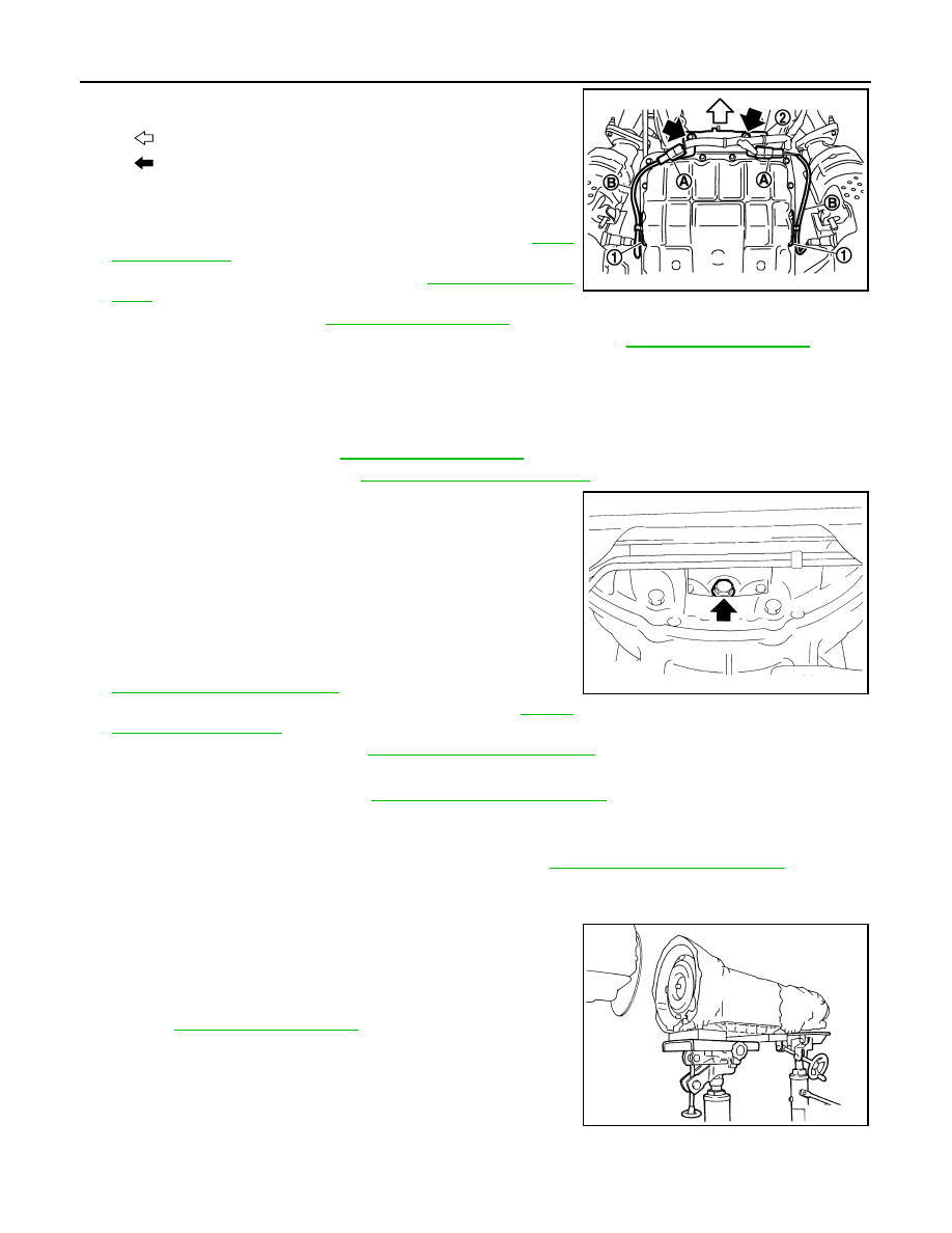
Disconnect heated oxygen sensor 2 harness connectors (A).
10. Remove heated oxygen sensor 2 harness (B) from clips (1).
11. Remove bracket (2) from transmission assembly.
12. Remove three way catalyst (right bank). Refer to
13. Remove front propeller shaft. Refer to
.
14. Remove control rod. Refer to
.
15. Remove crankshaft position sensor (POS) from A/T assembly. Refer to
.
CAUTION:
• Do not subject it to impact by dropping or hitting it.
• Do not disassemble.
• Do not allow metal filings, etc. to get on the sensor's front edge magnetic area.
• Do not place in an area affected by magnetism.
16. Remove starter motor. Refer to
.
17. Remove rear plate cover. Refer to
18. Turn crankshaft, and remove the four tightening bolts for drive
plate and torque converter.
CAUTION:
When turning the crankshaft, turn it clockwise as viewed
from the front of the engine.
19. Support A/T assembly with a transmission jack.
CAUTION:
When setting the transmission jack, be careful not to allow
it to collide against the drain plug.
20. Remove rear engine mounting member with power tool. Refer to
21. Remove engine mounting insulator (rear). Refer to
22. Remove dynamic damper. Refer to
23. Disconnect A/T assembly harness connector and harness clips.
24. Remove air breather hose. Refer to
.
25. Remove A/T fluid charging pipe from A/T assembly.
26. Remove O-ring from A/T fluid charging pipe.
27. Disconnect fluid cooler tube from the A/T assembly. Refer to
28. Plug up openings such as the A/T fluid charging pipe hole, etc.
29. Remove bolts fixing A/T assembly to engine assembly with power tool.
30. Remove A/T assembly with transfer assembly from vehicle.
CAUTION:
• Secure torque converter to prevent it from dropping.
• Secure A/T assembly to a transmission jack.
31. Remove transfer assembly from A/T assembly with power tool.
INSTALLATION
Note the following, and Install in the reverse order of removal.
: Vehicle front
: Bolt
SCIA8269E
JPDIA0044ZZ
SCIA2203E
TRANSMISSION ASSEMBLY
TM-197
< REMOVAL AND INSTALLATION >
[5AT: RE5R05A]
C
E
F
G
H
I
J
K
L
M
A
B
TM
N
O
P
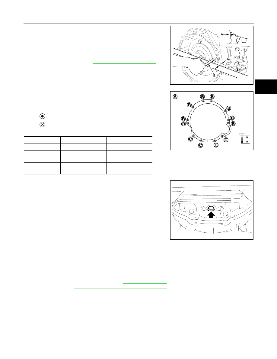
• When installing A/T assembly to the engine assembly, be sure to
check distance (A) to ensure it is within the reference value limit.
• When installing A/T assembly to the engine assembly, attach the
fixing bolts in accordance with the following standard.
• Align the positions of tightening bolts for drive plate with those of
the torque converter, and temporarily tighten the bolts. Then,
tighten the bolts with the specified torque.
CAUTION:
• When turning crankshaft, turn it clockwise as viewed from the
front of the engine.
• When tightening the tightening bolts for the torque converter
after fixing the crankshaft pulley bolts, be sure to confirm the
tightening torque of the crankshaft pulley mounting bolts.
Refer to
• Rotate crankshaft several turns and check to be sure that A/T
rotates freely without binding after converter is installed to
drive plate.
• Install crankshaft position sensor (POS). Refer to
.
AWD : Inspection
INFOID:0000000003130644
INSPECTION AFTER INSTALLATION
Check the following item after completing installation.
• A/T fluid leakage and A/T fluid level. Refer to
• A/T position. Refer to
TM-153, "AWD : Inspection and Adjustment"
B
: Scale
C
: Straightedge
Distance (A)
: Refer to
JPDIA0042ZZ
A
: View from vehicle front
: Transmission to engine
: Engine to transmission
Bolt symbol
B
C
Number of bolts
8
4
Bolt length
mm (in)
65 (2.56)
35 (1.38)
Tightening torque
N·m (kg-m, ft-lb)
75 (7.7, 55)
46.6 (4.8, 34)
JPDIA0043ZZ
JPDIA0044ZZ
TM-198
< DISASSEMBLY AND ASSEMBLY >
[5AT: RE5R05A]
TRANSMISSION ASSEMBLY
DISASSEMBLY AND ASSEMBLY
TRANSMISSION ASSEMBLY
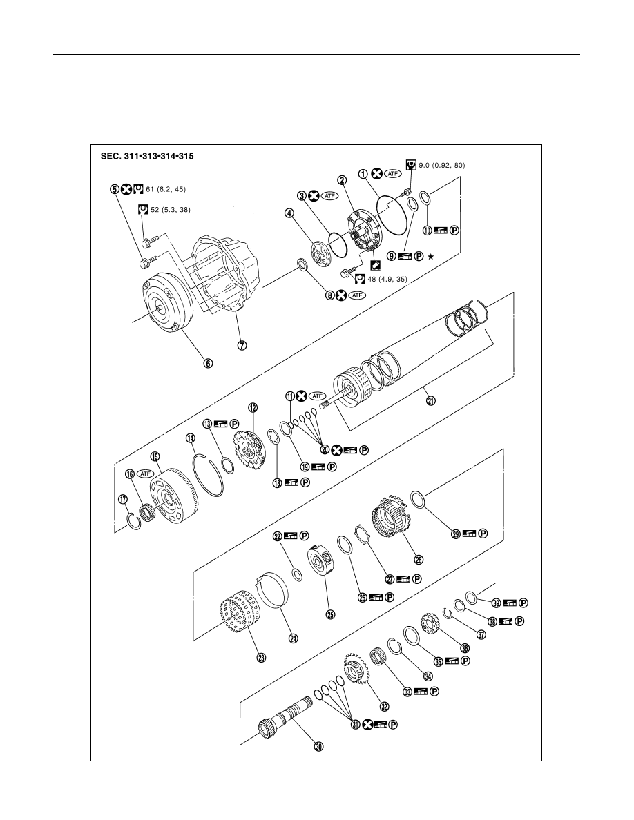
Exploded View
INFOID:0000000003130645
JPDIA0556GB

TRANSMISSION ASSEMBLY
TM-199
< DISASSEMBLY AND ASSEMBLY >
[5AT: RE5R05A]
C
E
F
G
H
I
J
K
L
M
A
B
TM
N
O
P
1.
O-ring
2.
Oil pump cover
3.
O-ring
4.
Oil pump housing
5.
Self-sealing bolt
6.
Torque converter
7.
Converter housing
8.
Oil pump housing oil seal
9.
Bearing race
10.
Needle bearing
11.
O-ring
12.
Front carrier assembly
13.
Needle bearing
14.
Snap ring
15.
Front sun gear
16.
3rd one-way clutch
17.
Snap ring
18.
Bearing race
19.
Needle bearing
20.
Seal ring
21.
Input clutch assembly
22.
Needle bearing
23.
Rear internal gear
24.
Brake band
25.
Mid carrier assembly
26.
Needle bearing
27.
Bearing race
28.
Rear carrier assembly
29.
Needle bearing
30.
Mid sun gear
31.
Seal ring
32.
Rear sun gear
33.
1st one-way clutch
34.
Snap ring
35.
Needle bearing
36.
High and low reverse clutch hub
37.
Snap ring
38.
Bearing race
39.
Needle bearing
: Apply Genuine RTV silicone sealant or equivalent. Refer to
GI-15, "Recommended Chemical Products and Sealants"
for symbols not described on the above.
Нет комментариевНе стесняйтесь поделиться с нами вашим ценным мнением.
Текст