Infiniti EX35. Manual — part 662
EC-390
< COMPONENT DIAGNOSIS >
[VQ35HR]
P1554 BATTERY CURRENT SENSOR
YES
>> GO TO 5.
NO
>> GO TO 4.
4.
DETECT MALFUNCTIONING PART
Check the following.
• Harness connectors F1, E3
• Harness for open between battery current sensor and ECM
>> Repair open circuit.
5.
CHECK SENSOR POWER SUPPLY CIRCUIT
Check harness for short to power and short to ground, between the following terminals.
Is the inspection result normal?
YES
>> GO TO 6.
NO
>> Repair short to ground or short to power in harness or connectors.
6.
CHECK COMPONENTS
Check the following.
• Crankshaft position sensor (POS) (Refer to
EC-255, "Component Inspection"
• Camshaft position sensor (PHASE) (bank 2) (Refer to
EC-260, "Component Inspection"
• Exhaust valve timing control position sensor (bank 2) (Refer to
EC-348, "Component Inspection"
.)
• EVAP control system pressure sensor (Refer to
EC-296, "Component Inspection"
.)
• Refrigerant pressure sensor (Refer to
Is the inspection result normal?
YES
>> GO TO 7.
NO
>> Replace malfunctioning component.
7.
CHECK APP SENSOR
EC-423, "Component Inspection"
Is the inspection result normal?
YES
>> GO TO 14.
NO
>> GO TO 8.
8.
REPLACE ACCELERATOR PEDAL ASSEMBLY
1.
Replace accelerator pedal assembly.
2.
Go to
EC-423, "Special Repair Requirement"
.
>> INSPECTION END
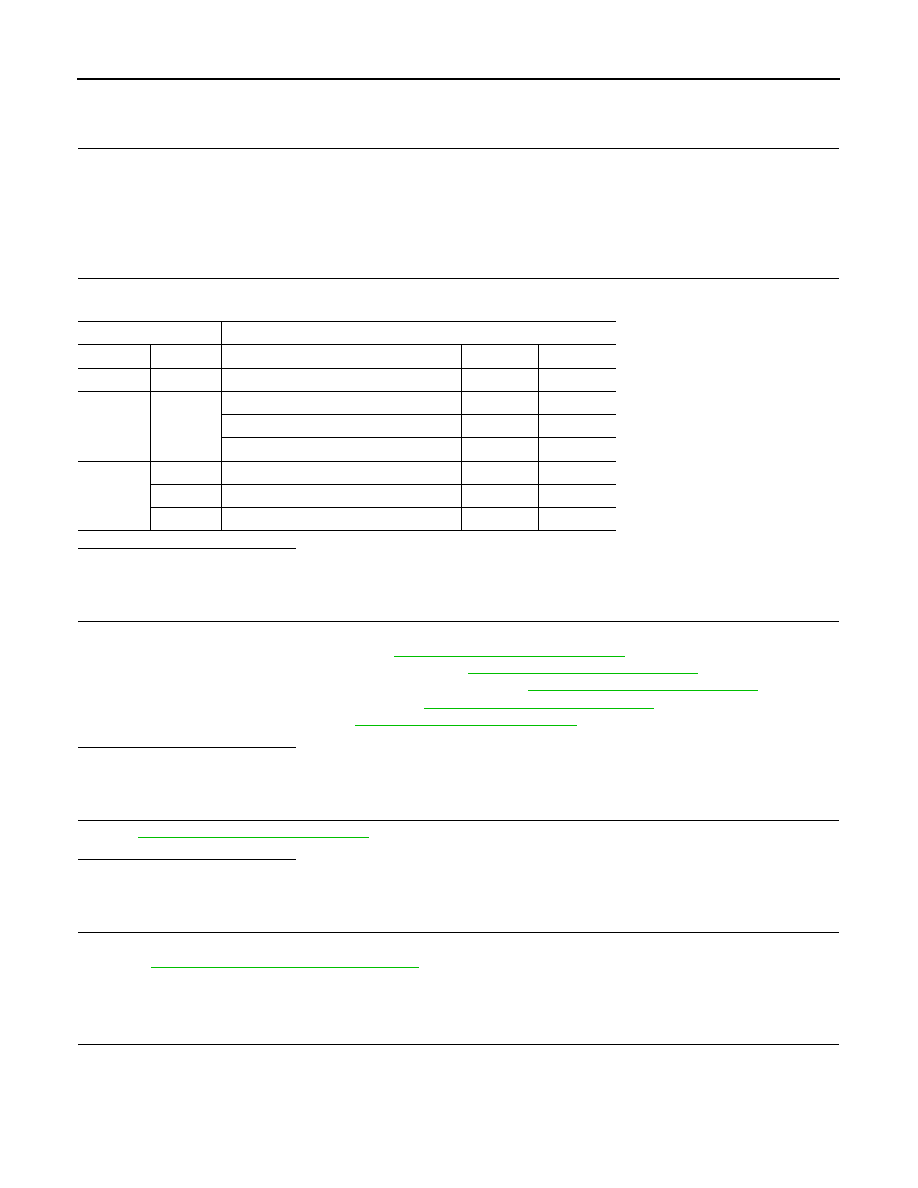
9.
CHECK BATTERY CURRENT SENSOR GROUND CIRCUIT FOR OPEN AND SHORT
1.
Turn ignition switch OFF.
2.
Disconnect ECM harness connector.
3.
Check the continuity between battery current sensor harness connector and ECM harness connector.
ECM
Sensor
Connector
Terminal
Name
Connector
Terminal
F101
46
CKP sensor (POS)
F2
1
F102
64
CMP sensor (PHASE) (bank 2)
F18
1
EVT control position sensor (bank 2)
F19
1
Battery current sensor
E21
1
M107
103
APP sensor
E112
6
107
EVAP control system pressure sensor
B252
3
111
Refrigerant pressure sensor
E77
3
P1554 BATTERY CURRENT SENSOR
EC-391
< COMPONENT DIAGNOSIS >
[VQ35HR]
C
D
E
F
G
H
I
J
K
L
M
A
EC
N
P
O
4.
Also check harness for short to ground and short to power.
Is the inspection result normal?
YES
>> GO TO 11.
NO
>> GO TO 10.
10.
DETECT MALFUNCTIONING PART
Check the following.
• Harness connectors F1, E3
• Harness for open or short between battery current sensor and ECM
>> Repair open circuit or short to ground or short to power in harness or connectors.
11.
CHECK BATTERY CURRENT SENSOR INPUT SIGNAL CIRCUIT FOR OPEN AND SHORT
1.
Check the continuity between battery current sensor harness connector and ECM harness connector.
2.
Also check harness for short to ground and short to power.
Is the inspection result normal?
YES
>> GO TO 13.
NO
>> GO TO 12.
12.
DETECT MALFUNCTIONING PART
Check the following.
• Harness connectors F1, E3
• Harness for open or short between battery current sensor and ECM
>> Repair open circuit or short to ground or short to power in harness or connectors.
13.
CHECK BATTERY CURRENT SENSOR
EC-391, "Component Inspection"
Is the inspection result normal?
YES
>> GO TO 14.
NO
>> Replace battery negative cable assembly.
14.
CHECK INTERMITTENT INCIDENT
GI-38, "Intermittent Incident"
.
>> INSPECTION END
Component Inspection
INFOID:0000000003133562
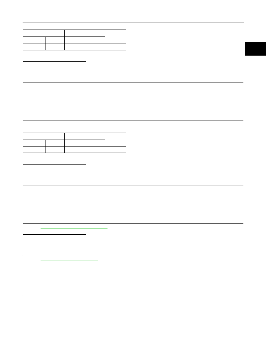
1.
CHECK BATTERY CURRENT SENSOR
1.
Turn ignition switch OFF.
2.
Reconnect harness connectors disconnected.
Battery current sensor
ECM
Continuity
Connector
Terminal
Connector
Terminal
E21
2
F102
95
Existed
Battery current sensor
ECM
Continuity
Connector
Terminal
Connector
Terminal
E21
3
F102
91
Existed
EC-392
< COMPONENT DIAGNOSIS >
[VQ35HR]
P1554 BATTERY CURRENT SENSOR
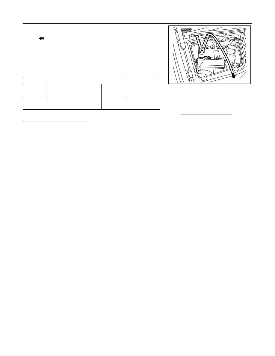
3.
Disconnect battery negative cable (1).
4.
Install jumper cable (A) between battery negative terminal and
body ground.
5.
Turn ignition switch ON.
6.
Check the voltage between ECM harness connector terminals
under the following conditions.
Before measuring the terminal voltage, confirm that the battery is fully charged. Refer to
.
Is the inspection result normal?
YES
>> INSPECTION END
NO
>> Replace battery negative cable assembly.
: To body ground
ECM
Voltage (V)
Connector
+
–
Terminal
Terminal
F102
91
(Battery current sensor signal)
95
Approx. 2.5
JMBIA0027ZZ

P1564 ASCD STEERING SWITCH
EC-393
< COMPONENT DIAGNOSIS >
[VQ35HR]
C
D
E
F
G
H
I
J
K
L
M
A
EC
N
P
O
P1564 ASCD STEERING SWITCH
Description
INFOID:0000000003133563
ASCD steering switch has variant values of electrical resistance for each button. ECM reads voltage variation
of switch, and determines which button is operated.
Refer to
for the ASCD function.
DTC Logic
INFOID:0000000003133564
DTC DETECTION LOGIC
NOTE:
If DTC P1564 is displayed with DTC P0605, first perform the trouble diagnosis for DTC P0605. Refer to
DTC CONFIRMATION PROCEDURE
1.
PRECONDITIONING
If DTC Confirmation Procedure has been previously conducted, always turn ignition switch OFF and wait at
least 10 seconds before conducting the next test.
>> GO TO 2.
2.
PERFORM DTC CONFIRMATION PROCEDURE
1.
Turn ignition switch ON and wait at least 10 seconds.
2.
Press MAIN switch for at least 10 seconds, then release it and wait at least 10 seconds.
3.
Press CANCEL switch for at least 10 seconds, then release it and wait at least 10 seconds.
4.
Press RESUME/ACCELERATE switch for at least 10 seconds, then release it and wait at least 10 sec-
onds.
5.
Press SET/COAST switch for at least 10 seconds, then release it and wait at least 10 seconds.
6.
Check DTC.
Is DTC detected?
YES
>> Go to
NO
>> INSPECTION END
Diagnosis Procedure
INFOID:0000000003133565
1.
CHECK GROUND CONNECTION
1.
Turn ignition switch OFF.
2.
Check ground connection M95. Refer to Ground Inspection in
Is the inspection result normal?
YES
>> GO TO 2.
NO
>> Repair or replace ground connection.
2.
CHECK ASCD STEERING SWITCH CIRCUIT
With CONSULT-III
1.
Turn ignition switch ON.
2.
Select “MAIN SW”, “CANCEL SW”, “RESUME/ACC SW” and “SET SW” in “DATA MONITOR” mode with
CONSULT-III.
DTC No.
Trouble diagnosis
name
DTC detecting condition
Possible cause
P1564
ASCD steering switch
• An excessively high voltage signal from the
ASCD steering switch is sent to ECM.
• ECM detects that input signal from the
ASCD steering switch is out of the specified
range.
• ECM detects that the ASCD steering switch
is stuck ON.
• Harness or connectors
(The switch circuit is open or shorted.)
• ASCD steering switch
• ECM
Нет комментариевНе стесняйтесь поделиться с нами вашим ценным мнением.
Текст