Infiniti EX35. Manual — part 663
EC-394
< COMPONENT DIAGNOSIS >
[VQ35HR]
P1564 ASCD STEERING SWITCH
3.
Check each item indication under the following conditions.
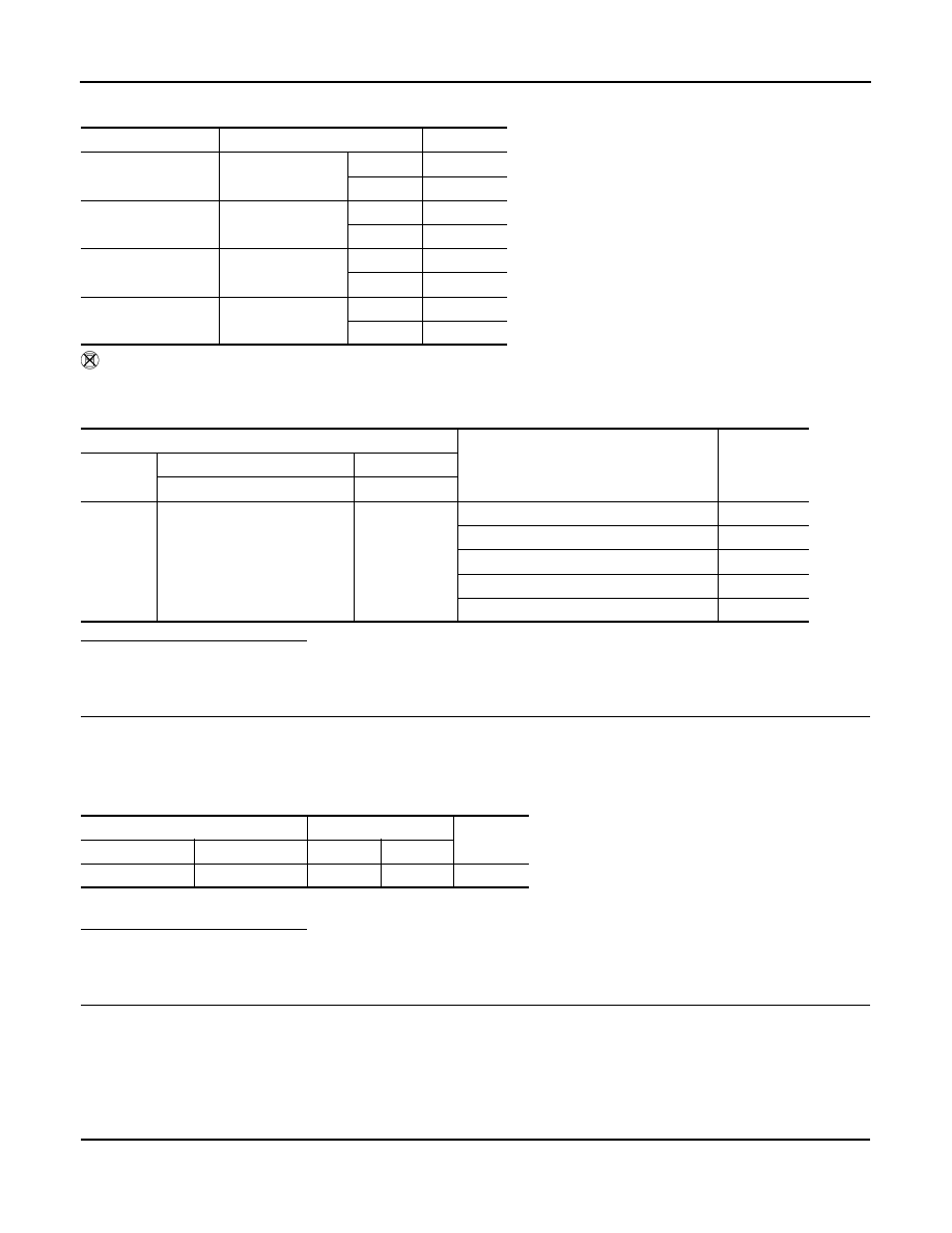
Without CONSULT-III
1.
Turn ignition switch ON.
2.
Check the voltage between ECM harness connector terminals under the following conditions.
Is the inspection result normal?
YES
>> GO TO 8.
NO
>> GO TO 3.
3.
CHECK ASCD STEERING SWITCH GROUND CIRCUIT FOR OPEN AND SHORT
1.
Turn ignition switch OFF.
2.
Disconnect ECM harness connector.
3.
Disconnect combination switch harness connector.
4.
Check the continuity between combination switch and ECM harness connector.
5.
Also check harness for short to ground and short to power.
Is the inspection result normal?
YES
>> GO TO 5.
NO
>> GO TO 4.
4.
DETECT MALFUNCTIONING PART
Check the following.
• Combination switch (spiral cable)
• Harness for open and short between ECM and combination switch
>> Repair open circuit or short to ground or short to power in harness or connectors.
5.
CHECK ASCD STEERING SWITCH INPUT SIGNAL CIRCUIT FOR OPEN AND SHORT
1.
Check the continuity between combination switch and ECM harness connector.
Monitor item
Condition
Indication
MAIN SW
MAIN switch
Pressed
ON
Released
OFF
CANCEL SW
CANCEL switch
Pressed
ON
Released
OFF
RESUME/ACC SW
RESUME/ACCEL-
ERATE switch
Pressed
ON
Released
OFF
SET SW
SET/COAST switch
Pressed
ON
Released
OFF
ECM
Condition
Voltage (V)
Connector
+
–
Terminal
Terminal
M107
101
(ASCD steering switch signal)
108
MAIN switch: Pressed
Approx. 0
CANCEL switch: Pressed
Approx. 1
SET/COAST switch: Pressed
Approx. 2
RESUME/ACCELERATE switch: Pressed
Approx. 3
All ASCD steering switches: Released
Approx. 4
Combination switch
ECM
Continuity
Connector
Terminal
Connector
Terminal
M303
16
M107
108
Existed
P1564 ASCD STEERING SWITCH
EC-395
< COMPONENT DIAGNOSIS >
[VQ35HR]
C
D
E
F
G
H
I
J
K
L
M
A
EC
N
P
O
2.
Also check harness for short to ground and short to power.
Is the inspection result normal?
YES
>> GO TO 7.
NO
>> GO TO 6.
6.
DETECT MALFUNCTIONING PART
Check the following.
• Combination switch (spiral cable)
• Harness for open and short between ECM and combination switch
>> Repair open circuit or short to ground or short to power in harness or connectors.
7.
CHECK ASCD STEERING SWITCH
EC-395, "Component Inspection"
Is the inspection result normal?
YES
>> GO TO 8.
NO
>> Replace ASCD steering switch.
8.
CHECK INTERMITTENT INCIDENT
GI-38, "Intermittent Incident"
.
>> INSPECTION END
Component Inspection
INFOID:0000000003133566
1.
CHECK ASCD STEERING SWITCH
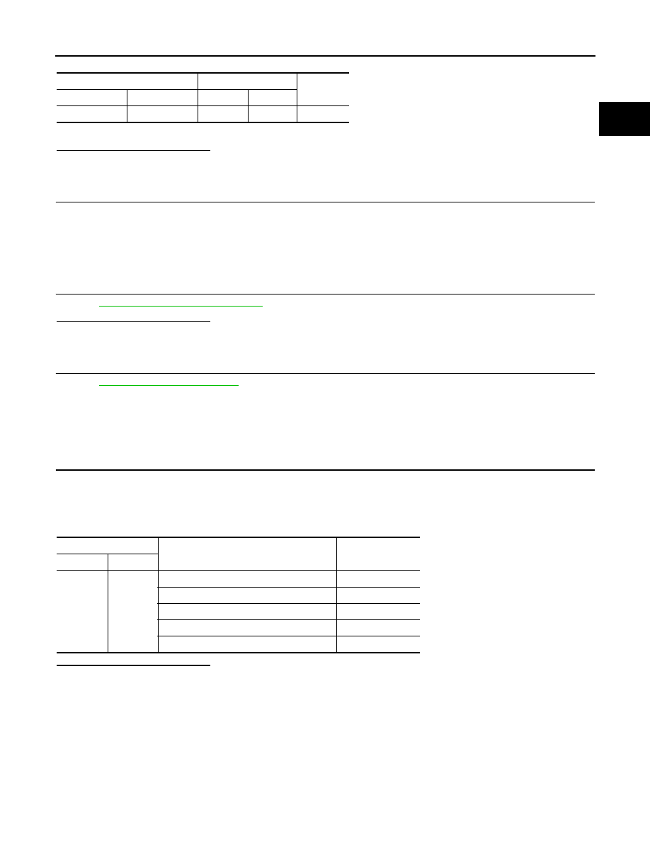
1.
Turn ignition switch OFF.
2.
Disconnect combination switch (spiral cable) harness connector M303.
3.
Check resistance between combination switch harness connector terminals under the following condi-
tions.
Is the inspection result normal?
YES
>> INSPECTION END
NO
>> Replace ASCD steering switch
Combination switch
ECM
Continuity
Connector
Terminal
Connector
Terminal
M303
13
M107
101
Existed
Combination switch
Condition
Resistance (
Ω
)
Connector
Terminals
M303
13 and 16
MAIN switch: Pressed
Approx. 0
CANCEL switch: Pressed
Approx. 250
SET/COAST switch: Pressed
Approx. 660
RESUME/ACCELERATE switch: Pressed
Approx. 1,480
All ASCD steering switches: Released
Approx. 4,000

EC-396
< COMPONENT DIAGNOSIS >
[VQ35HR]
P1564 ICC STEERING SWITCH
P1564 ICC STEERING SWITCH
Description
INFOID:0000000003133567
ICC steering switch has variant values of electrical resistance for each button. ECM reads voltage variation of
switch, and determines which button is operated.
Refer to
for the ICC function.
DTC Logic
INFOID:0000000003133568
DTC DETECTION LOGIC
NOTE:
If DTC P1564 is displayed with DTC P0605, first perform the trouble diagnosis for DTC P0605. Refer to
DTC CONFIRMATION PROCEDURE
1.
PRECONDITIONING
If DTC Confirmation Procedure has been previously conducted, always turn ignition switch OFF and wait at
least 10 seconds before conducting the next test.
>> GO TO 2.
2.
PERFORM DTC CONFIRMATION PROCEDURE
1.
Turn ignition switch ON and wait at least 10 seconds.
2.
Press MAIN switch for at least 10 seconds, then release it and wait at least 10 seconds.
3.
Press CANCEL switch for at least 10 seconds, then release it and wait at least 10 seconds.
4.
Press RESUME/ACCELERATE switch for at least 10 seconds, then release it and wait at least 10 sec-
onds.
5.
Press SET/COAST switch for at least 10 seconds, then release it and wait at least 10 seconds.
6.
Press DISTANCE switch for at least 10 seconds, then release it and wait at least 10 seconds.
7.
Press LDP switch for at least 10 seconds, then release it at wait at least 10 seconds.
8.
Check DTC.
Is DTC detected?
YES
>> Go to
NO
>> INSPECTION END
Diagnosis Procedure
INFOID:0000000003133569
1.
CHECK GROUND CONNECTION
1.
Turn ignition switch OFF.
2.
Check ground connection M95. Refer to Ground Inspection in
Is the inspection result normal?
YES
>> GO TO 2.
NO
>> Repair or replace ground connection.
2.
CHECK ICC STEERING SWITCH CIRCUIT
With CONSULT-III
1.
Turn ignition switch ON.
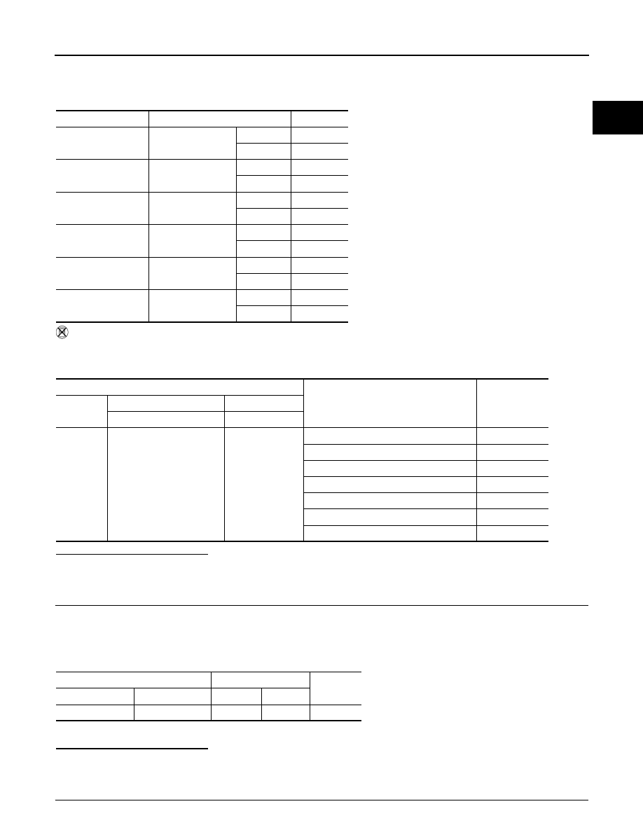
DTC No.
Trouble diagnosis
name
DTC detecting condition
Possible cause
P1564
ICC steering switch
• An excessively high voltage signal from the
ICC steering switch is sent to ECM.
• ECM detects that input signal from the ICC
steering switch is out of the specified range.
• ECM detects that the ICC steering switch is
stuck ON.
• Harness or connectors
(The switch circuit is open or shorted.)
• ICC steering switch
• ECM
P1564 ICC STEERING SWITCH
EC-397
< COMPONENT DIAGNOSIS >
[VQ35HR]
C
D
E
F
G
H
I
J
K
L
M
A
EC
N
P
O
2.
Select “MAIN SW”, “CANCEL SW”, “RESUME/ACC SW”, “SET SW” and “DIST SW” and “LDP SW” in
“DATA MONITOR” mode with CONSULT-III.
3.
Check each item indication under the following conditions.
Without CONSULT-III
1.
Turn ignition switch ON.
2.
Check the voltage between ECM harness connector terminals under the following conditions.
Is the inspection result normal?
YES
>> GO TO 8.
NO
>> GO TO 3.
3.
CHECK ICC STEERING SWITCH GROUND CIRCUIT FOR OPEN AND SHORT
1.
Turn ignition switch OFF.
2.
Disconnect ECM harness connector.
3.
Disconnect combination switch harness connector.
4.
Check the continuity between combination switch and ECM harness connector.
5.
Also check harness for short to ground and short to power.
Is the inspection result normal?
YES
>> GO TO 5.
NO
>> GO TO 4.
4.
DETECT MALFUNCTIONING PART
Monitor item
Condition
Indication
MAIN SW
MAIN switch
Pressed
ON
Released
OFF
CANCEL SW
CANCEL switch
Pressed
ON
Released
OFF
RESUME/ACC SW
RESUME/ACCEL-
ERATE switch
Pressed
ON
Released
OFF
SET SW
SET/COAST switch
Pressed
ON
Released
OFF
DIST SW
DISTANCE switch
Pressed
ON
Released
OFF
LDP SW
LDP switch
Pressed
ON
Released
OFF
ECM
Condition
Voltage (V)
Connector
+
–
Terminal
Terminal
M107
101
(ICC steering switch signal)
108
MAIN switch: Pressed
Approx. 0
LDP switch: Pressed
Approx. 1.1
CANCEL switch: Pressed
Approx. 1.9
DISTANCE switch: Pressed
Approx. 2.6
SET/COAST switch: Pressed
Approx. 3.3
RESUME/ACCELERATE switch: Pressed
Approx. 3.8
All ICC steering switches: Released
Approx. 4.3
Combination switch
ECM
Continuity
Connector
Terminal
Connector
Terminal
M303
16
M107
108
Existed
Нет комментариевНе стесняйтесь поделиться с нами вашим ценным мнением.
Текст