Infiniti EX35. Manual — part 180
AV
DIAGNOSIS SYSTEM (AV CONTROL UNIT)
AV-501
< FUNCTION DIAGNOSIS >
[BOSE AUDIO WITH NAVIGATION]
C
D
E
F
G
H
I
J
K
L
M
B
A
O
P
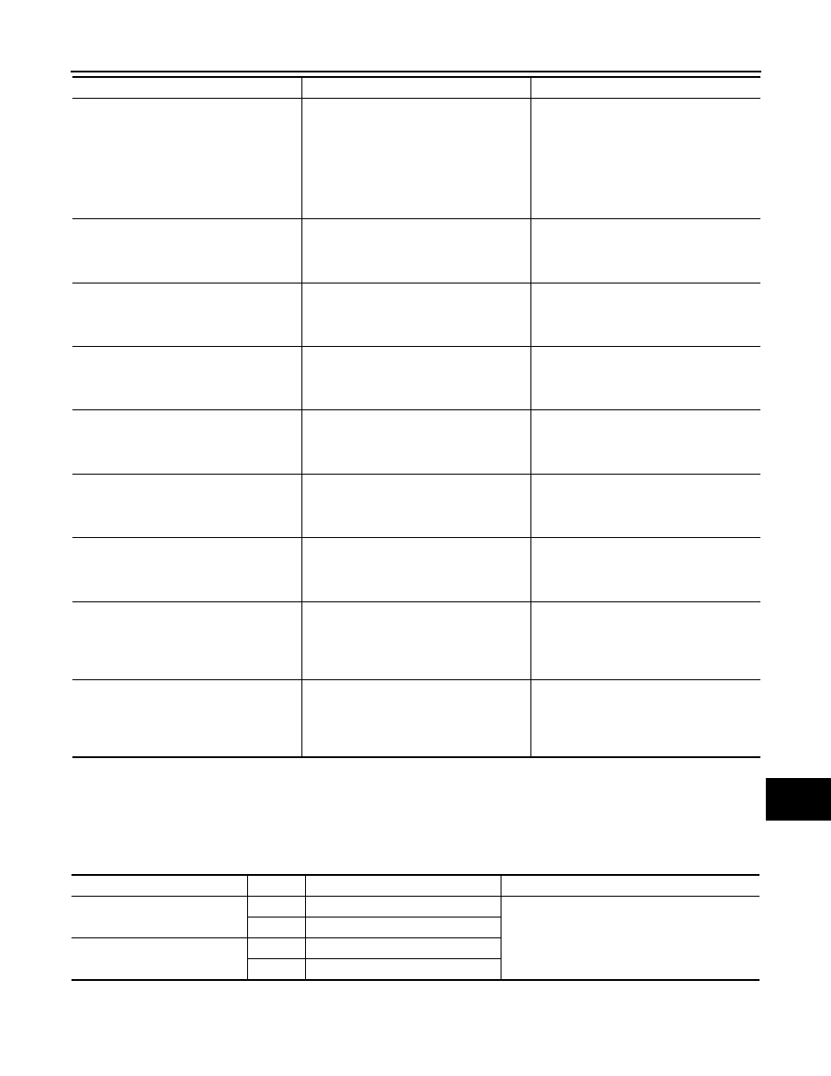
DATA MONITOR
ALL SIGNALS
• Displays the status of the following vehicle signals inputted into AV control unit.
• For each signal, actual signal can be compared with the condition recognized on the system.
• AV COMM CIRCUIT [U1300]
• SONAR CONN [U125C]
When either one of the following items
are detected:
• Sonar control unit power supply or
ground circuit malfunction are detected.
• Malfunction is detected in the AV com-
munication circuits between sonar con-
trol unit and the junction between AV
control unit and multifunction switch.
• Sonar control unit power supply and
ground circuits.
• AV communication circuits between so-
nar control unit and the junction between
AV control unit and multifunction switch.
• AV COMM CIRCUIT [U1300]
• SWITCH CONN [U1240]
• IPod CONN [U1254]
Malfunction is detected in the AV communi-
cation circuits between AV control unit and
the junction between multifunction switch
and iPod adapter.
AV control unit and the junction between
multifunction switch and iPod adapter.
• AV COMM CIRCUIT [U1300]
• REAR CAMERA LAN CONN [U1252]
• IPod CONN [U1254]
Malfunction is detected in the AV communi-
cation circuits between camera control unit
and the junction between AV control unit
and multifunction switch.
AV communication circuits between cam-
era control unit and the junction between
AV control unit and multifunction switch.
• AV COMM CIRCUIT [U1300]
• SWITCH CONN [U1240]
• REAR CAMERA LAN CONN [U1252]
• IPod CONN [U1254]
Malfunction is detected in the AV communi-
cation circuits between AV control unit and
the junction between camera control unit
and multifunction switch.
AV communication circuits between AV
control unit and the junction between cam-
era control unit and multifunction switch.
• AV COMM CIRCUIT [U1300]
• IPod CONN [U1254]
• AROUND CAMERA CONN [U125B]
Malfunction is detected in the AV communi-
cation circuits between around view moni-
tor control unit and the junction between AV
control unit and multifunction switch.
AV communication circuits between around
view monitor control unit and the junction
between AV control unit and multifunction
switch.
• AV COMM CIRCUIT [U1300]
• SWITCH CONN [U1240]
• IPod CONN [U1254]
• AROUND CAMERA CONN [U125B]
Malfunction is detected in the AV communi-
cation circuits between AV control unit and
the junction between around view monitor
control unit and multifunction switch.
AV communication circuits between AV
control unit and the junction between
around view monitor control unit and multi-
function switch.
• AV COMM CIRCUIT [U1300]
• INTERNAL COMM [U121F]
• SWITCH CONN [U1240]
• IPod CONN [U1254]
Malfunction is detected in the AV communi-
cation circuits.
Check and repair the short circuit in AV
communication circuits.
• AV COMM CIRCUIT [U1300]
• INTERNAL COMM [U121F]
• SWITCH CONN [U1240]
• REAR CAMERA LAN CONN [U1252]
• IPod CONN [U1254]
Malfunction is detected in the AV communi-
cation circuits.
Check and repair the short circuit in AV
communication circuits.
• AV COMM CIRCUIT [U1300]
• INTERNAL COMM [U121F]
• SWITCH CONN [U1240]
• IPod CONN [U1254]
• AROUND CAMERA CONN [U125B]
Malfunction is detected in the AV communi-
cation circuits.
Check and repair the short circuit in AV
communication circuits.
Error item
Description
Possible malfunction factor/Action to take
Display Item
Display
Vehicle status
Remarks
VHCL SPD SIG
On
Vehicle speed > 0 km/h (0 MPH)
Changes in indication may be delayed. This is
normal.
Off
Vehicle speed = 0 km/h (0 MPH)
PKB SIG
On
Parking brake is applied.
Off
Parking brake is released.
AV-502
< FUNCTION DIAGNOSIS >
[BOSE AUDIO WITH NAVIGATION]
DIAGNOSIS SYSTEM (AV CONTROL UNIT)
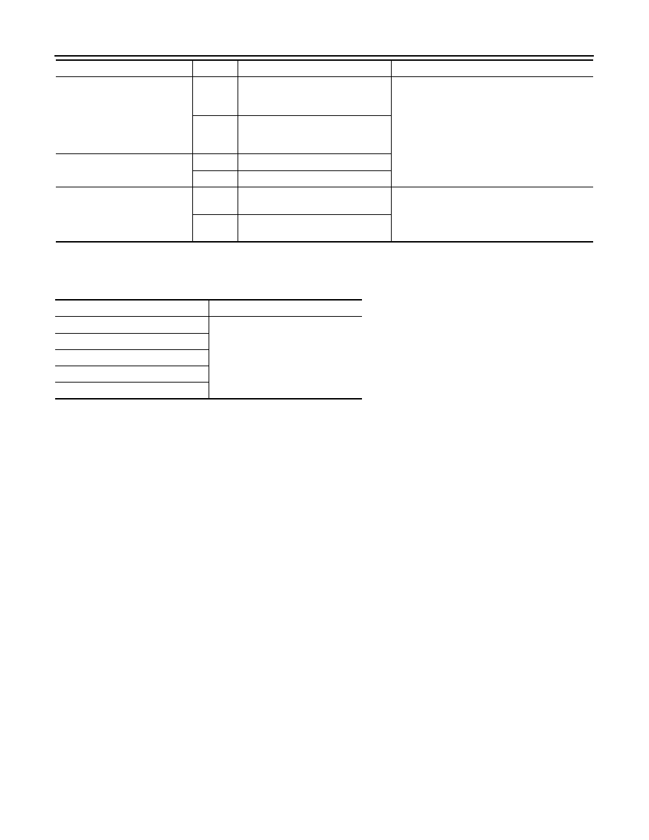
SELECTION FROM MENU
Allows the technician to select which vehicle signals should be displayed and displays the status of the
selected vehicle signals.
ILLUM SIG
On
Block the light beam from the auto
light optical sensor when the light
SW is ON.
—
Off
Expose the auto light optical sensor
to light when the light SW is OFF or
ON.
IGN SIG
On
Ignition switch ON
Off
Ignition switch in the ACC position
REV SIG
On
Shift the selector lever to the “R” po-
sition
Changes in indication may be delayed. This is
normal.
Off
Shift the selector lever to a position
other than the “R” position
Display Item
Display
Vehicle status
Remarks
Item to be selected
Description
VHCL SPD SIG
The same as when “ALL SIGNALS”
is selected.
PKB SIG
ILLUM SIG
IGN SIG
REV SIG
AV
DIAGNOSIS SYSTEM (AROUND VIEW MONITOR CONTROL UNIT)
AV-503
< FUNCTION DIAGNOSIS >
[BOSE AUDIO WITH NAVIGATION]
C
D
E
F
G
H
I
J
K
L
M
B
A
O
P
DIAGNOSIS SYSTEM (AROUND VIEW MONITOR CONTROL UNIT)
Diagnosis Description
INFOID:0000000003390932
The diagnosis function of around view monitor control unit is displayed when selecting “Camera Cont.” of Con-
firmation/Adjustment mode in the multi AV system.
Around view monitor control unit diagnosis item
CAUTION:
*: Never perform other operations for approximately 10 seconds after performing "Initialize Camera Image Calibration".
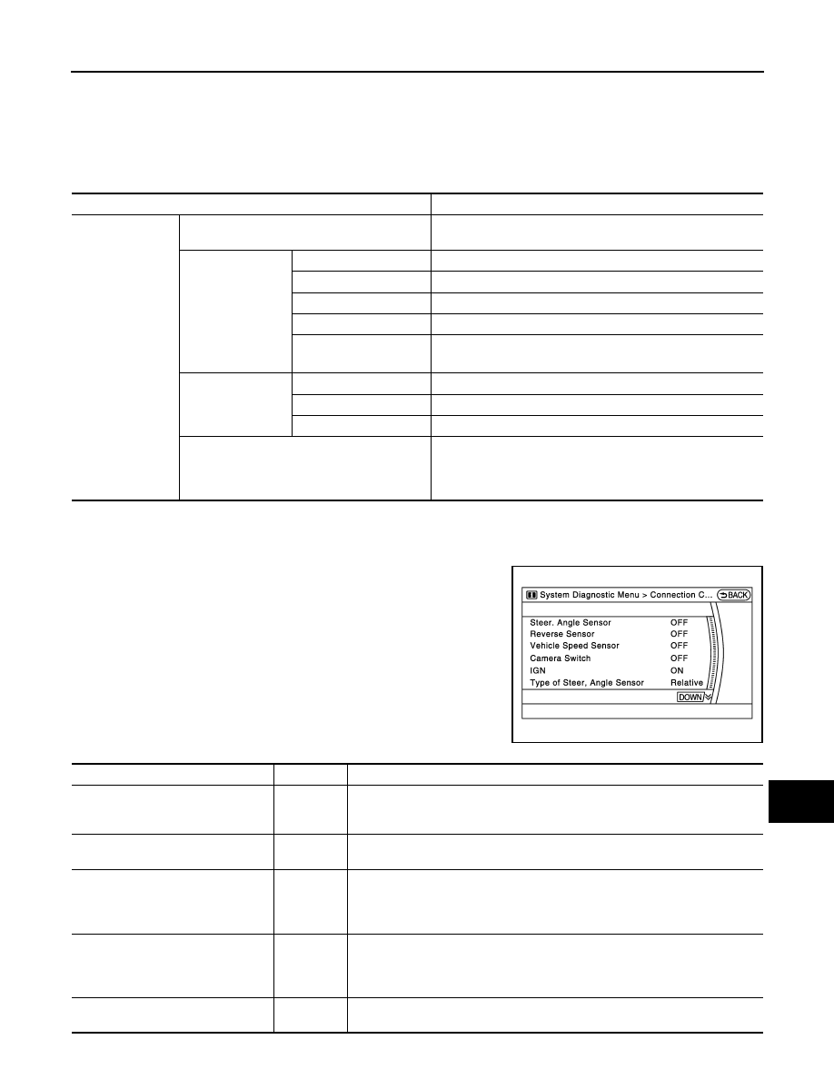
Connection Confirmation
The status of signals inputted to around view monitor control unit can
be checked.
Connection Confirmation item list
AV control unit Confirmation/Adjustment mode
Function
Camera Cont.
Connection Confirmation
The status of signals input to around view monitor control unit
can be checked.
Calibrating Cam-
era Image
Rear Camera
Performs the calibration of rear camera.
Pass-Side Camera
Performs the calibration of side camera LH.
Front Camera
Performs the calibration of front camera.
Dr-Side Camera
Performs the calibration of side camera.
Initialize Camera Image
Calibration
*
The calibration can be initialized to NISSAN factory shipment
condition.
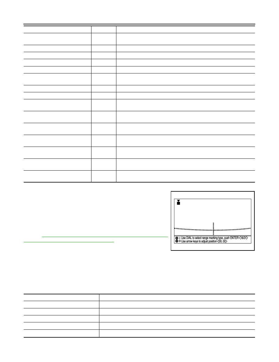
Correct Draw Line
of Camera Image
Rear View
The position of rear view guiding line can be changed.
Front-Side View
The position of Front-Side view guiding line can be changed.
Front View
The position of front view guiding line can be changed.
Fine Tuning of Birds-Eye View
• The confirmation and adjustment of the difference between
each camera can be performed.
• The system changes to the ZOOM function by the operation
of shift and the ZOOM ratio of each camera can be changed.
JSNIA1057GB
Diagnosis item
Display
Description
Steer. Angle Sensor
ON/OFF
• Input status of steering angle sensor is displayed by ON/OFF.
• When all of steering signals 1, 2, and 3 are input, it is turned ON. It remains
ON until connection confirmation mode is stopped.
Reverse Sensor
ON/OFF
Input status of reverse signal inputted to around view monitor control unit is dis-
played by ON/OFF in real time.
Vehicle Speed Sensor
ON/OFF
• Input status of vehicle speed signal inputted to around view monitor control
unit is displayed by ON/OFF.
• When the vehicle speed signal is input, it is turned ON. It remains ON until con-
nection confirmation mode is stopped.
Camera Switch
ON/OFF
• The status of camera switch signal received via AV communication from AV
control unit is displayed by ON/OFF.
• When the camera switch signal is received once, it is turned ON. It remains
ON until connection confirmation mode is stopped.
IGN
ON/OFF
Input status of ignition signal inputted to around view monitor control unit is dis-
played by ON/OFF in real time.
AV-504
< FUNCTION DIAGNOSIS >
[BOSE AUDIO WITH NAVIGATION]
DIAGNOSIS SYSTEM (AROUND VIEW MONITOR CONTROL UNIT)
Calibrating Camera Image
• Perform the calibration of camera image caused by the incorrect
mounting position of each camera, etc. Always perform calibration
after performing the following work.
- When each camera or each camera mount (door mirror, front grille,
etc.) is removed
- When replacing around view monitor control unit
• When performing the calibration initialization, it can be set to the
NISSAN factory shipment condition.
Refer to
AV-438, "CALIBRATING CAMERA IMAGE (AROUND VIEW
MONITOR) : Special Repair Requirement"
for the calibration proce-
dure.
Calibrating Camera Image item
CAUTION:
*: Never perform other operations for approximately 10 seconds after performing "Initialize Camera Image Calibration".
Type of Steer. Angle Sensor
Relative
The input type of steering angle sensor is displayed. (“Relative” is displayed on
this model.)
Type of Steer. Gear ratio
1
The type of steering gear ratio is displayed. (“1” is displayed on this model.)
Left or Right Steer.
Left
The steering position is displayed. (“Left” is displayed on this model.)
Rear Camera Image Output signal
OK / NG
The input status of rear camera image signal is displayed by OK/NG in real time.
Rear Camera COMM Status
OK / NG
The communication status with rear camera is displayed by OK/NG in real time.
Rear Camera COMM Line
OK / NG
The status of communication line with rear camera is displayed by OK/NG in real
time.
Front Camera Image Output signal
OK / NG
The input status of front camera image signal is displayed by OK/NG in real time.
Front Camera COMM Status
OK / NG
The communication status with front camera is displayed by OK/NG in real time.
Front Camera COMM Line
OK / NG
The status of communication line with front camera is displayed by OK/NG in real
time.
Pass-Side Camera Image Output sig-
nal
OK / NG
The input status of side camera RH image signal is displayed by OK/NG in real
time.
Pass-Side Camera COMM Status
OK / NG
The communication status with side camera RH is displayed by OK/NG in real
time.
Pass-Side Camera COMM Line
OK / NG
The status of communication line with side camera RH is displayed by OK/NG in
real time.
Dr-Side Camera Image Output signal
OK / NG
The input status of side camera LH image signal is displayed by OK/NG in real
time.
Dr-Side Camera COMM Status
OK / NG
The communication status with side camera LH is displayed by OK/NG in real
time.
Dr-Side Camera COMM Line
OK / NG
The status of communication line with side camera LH is displayed by OK/NG in
real time.
Diagnosis item
Display
Description
Adjustment range
Rotating direction
: 31 patterns (16 on the
center)
Upper/lower direction
:
−
99 – 99
Left/right direction
:
−
99 – 99
JSNIA1053GB
Items
Description
Rear Camera
Performs the calibration of rear camera.
Pass-Side Camera
Performs the calibration of side camera RH.
Front Camera
Performs the calibration of front camera.
Dr-Side Camera
Performs the calibration of side camera LH.
Initialize Camera Image Calibration
*
The calibration can be initialized to the factory shipment setting.
Нет комментариевНе стесняйтесь поделиться с нами вашим ценным мнением.
Текст