Infiniti EX35. Manual — part 178

AV
DIAGNOSIS SYSTEM (AV CONTROL UNIT)
AV-493
< FUNCTION DIAGNOSIS >
[BOSE AUDIO WITH NAVIGATION]
C
D
E
F
G
H
I
J
K
L
M
B
A
O
P
Front Display Connection Error
When either one of the following items
are detected:
• Display unit power supply or ground cir-
cuits malfunction are detected.
• Malfunction is detected in the communi-
cation circuits between AV control unit
and display unit.
• Display unit power supply and ground
circuits.
• Communication circuits between AV con-
trol unit and display unit.
GPS Antenna Error
GPS antenna connection malfunction is de-
tected.
GPS antenna.
Camera Control Unit Connection Error
Malfunction is detected in the camera con-
nection recognition circuit between AV con-
trol unit and camera control unit.
Camera-connection recognition circuit be-
tween AV control unit and camera control
unit.
XM Antenna Connection Error
Poor connection is detected in satellite ra-
dio antenna.
• Satellite radio antenna feeder.
• Satellite radio antenna.
• AV COMM CIRCUIT
• Internal Communication Error
When either one of the following items
are detected:
• AV control unit power supply or ground
circuits malfunction are detected.
• AV control unit malfunction is detected.
• AV control unit power supply and ground
circuits.
• When there is no malfunction, AV control
unit is malfunctioning.
• AV COMM CIRCUIT
• Switches Connection Error
WITHOUT REAR VIEW MONITOR AND
AROUND VIEW MONITOR
When either one of the following items
are detected:
• Multifunction switch power supply or
ground circuits malfunction are detected.
• Malfunction is detected in the AV com-
munication circuits between multifunc-
tion switch and the junction between AV
control unit and iPod adapter.
• Multifunction switch power supply and
ground circuits.
• AV communication circuits between mul-
tifunction switch and the junction be-
tween AV control unit and iPod adapter.
WITH REAR VIEW MONITOR
When either one of the following items
are detected:
• Multifunction switch power supply or
ground circuits malfunction are detected.
• Malfunction is detected in the AV com-
munication circuits between multifunc-
tion switch and the junction between AV
control unit and camera control unit.
• Multifunction switch power supply and
ground circuits.
• AV communication circuits between mul-
tifunction switch and the junction be-
tween AV control unit and camera control
unit.
WITH AROUND VIEW MONITOR
When either one of the following items
are detected:
• Multifunction switch power supply or
ground circuits malfunction are detected.
• Malfunction is detected in the AV com-
munication circuits between multifunc-
tion switch and the junction between AV
control unit and around view monitor
control unit.
• Multifunction switch power supply and
ground circuits.
• AV communication circuits between mul-
tifunction switch and the junction be-
tween AV control unit and around view
monitor control unit.
• AV COMM CIRCUIT
• Rearview Camera Connection Error
Camera control unit power supply or
ground circuits malfunction is detected.
Camera control unit power supply and
ground circuits.
Error item
Detection logic
Possible malfunction factor/Action to take

AV-494
< FUNCTION DIAGNOSIS >
[BOSE AUDIO WITH NAVIGATION]
DIAGNOSIS SYSTEM (AV CONTROL UNIT)
• AV COMM CIRCUIT
• iPod Connection Error
WITHOUT REAR VIEW MONITOR AND
AROUND VIEW MONITOR
When either one of the following items
are detected:
• iPod adapter power supply or ground cir-
cuits malfunction are detected.
• Malfunction is detected in the AV com-
munication circuits between camera con-
trol unit and iPod adapter.
WITHOUT REAR VIEW MONITOR AND
AROUND VIEW MONITOR
• iPod adapter power supply and ground
circuits.
• AV communication circuits between mul-
tifunction switch and iPod adapter.
WITH REAR VIEW MONITOR
When either one of the following items
are detected:
• iPod adapter power supply or ground cir-
cuits malfunction are detected.
• Malfunction is detected in the AV com-
munication circuits between camera con-
trol unit and iPod adapter.
WITH REAR VIEW MONITOR
• iPod adapter power supply and ground
circuits.
• AV communication circuits between cam-
era control unit and iPod adapter.
WITH AROUND VIEW MONITOR
When either one of the following items
are detected:
• iPod adapter power supply or ground cir-
cuits malfunction are detected.
• Malfunction is detected in the AV com-
munication circuits between around view
monitor control unit and iPod adapter.
WITH AROUND VIEW MONITOR
• iPod adapter power supply and ground
circuits.
• AV communication circuits between
around view monitor control unit and
iPod adapter.
• AV COMM CIRCUIT
• AVM Connection Error
Around view monitor control unit power
supply or ground circuits malfunction is de-
tected.
Around view monitor control unit power
supply and ground circuits.
• AV COMM CIRCUIT
• AVM Sonar Connection Error
When either one of the following items
are detected:
• Sonar control unit power supply or
ground circuits malfunction are detected.
• Malfunction is detected in the AV com-
munication circuits between sonar con-
trol unit and the junction between AV
control unit and multifunction switch.
• Sonar control unit power supply and
ground circuits.
• AV communication circuits between so-
nar control unit and the junction between
AV control unit multifunction switch.
• AV COMM CIRCUIT
• Switches Connection Error
• iPod Connection Error
Malfunction is detected in the AV communi-
cation circuits between AV control unit and
the junction between multifunction and
iPod adapter.
AV communication circuits between AV
control unit and the junction between multi-
function and iPod adapter.
• AV COMM CIRCUIT
• Rearview Camera Connection Error
• iPod Connection Error
Malfunction is detected in the AV communi-
cation circuits between camera control unit
and the junction between AV control unit
and multifunction switch.
AV communication circuits between cam-
era control unit and the junction between
AV control unit and multifunction switch.
• AV COMM CIRCUIT
• Switches Connection Error
• Rearview Camera Connection Error
• iPod Connection Error
Malfunction is detected in the AV communi-
cation circuits between AV control unit and
the junction between camera control unit
and multifunction switch.
AV communication circuits between AV
control unit and the junction between cam-
era control unit and multifunction switch.
• AV COMM CIRCUIT
• iPod Connection Error
• AVM Connection Error
Malfunction is detected in the AV communi-
cation circuits between around view moni-
tor control unit and the junction between AV
control unit and multifunction switch.
AV communication circuits between around
view monitor control unit and the junction
between AV control unit and multifunction
switch.
• AV COMM CIRCUIT
• Switches Connection Error
• iPod Connection Error
• AVM Connection Error
Malfunction is detected in the AV communi-
cation circuits between AV control unit and
the junction between around view monitor
control unit and multifunction switch.
AV communication circuits between AV
control unit and the junction between
around view monitor control unit and multi-
function switch.
Error item
Detection logic
Possible malfunction factor/Action to take
AV
DIAGNOSIS SYSTEM (AV CONTROL UNIT)
AV-495
< FUNCTION DIAGNOSIS >
[BOSE AUDIO WITH NAVIGATION]
C
D
E
F
G
H
I
J
K
L
M
B
A
O
P
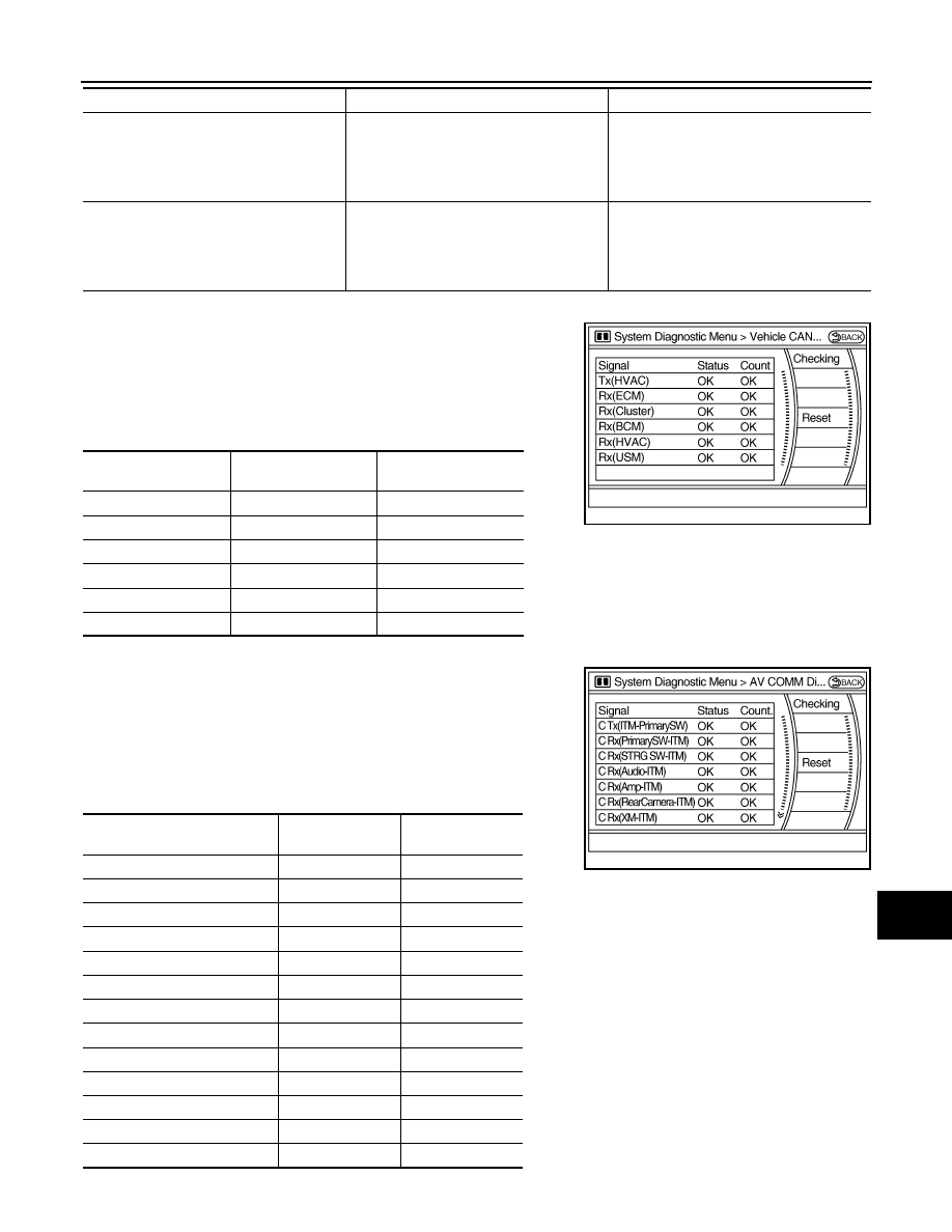
Vehicle CAN Diagnosis
• CAN communication status and error counter is displayed.
• The error counter displays “OK” if any malfunction was not
detected in the past and displays “0” if a malfunction is detected. It
increases by 1 if the condition is normal at the next ignition switch
ON cycle. The upper limit of the counter is 39.
• The error counter is erased if “Reset” is pressed.
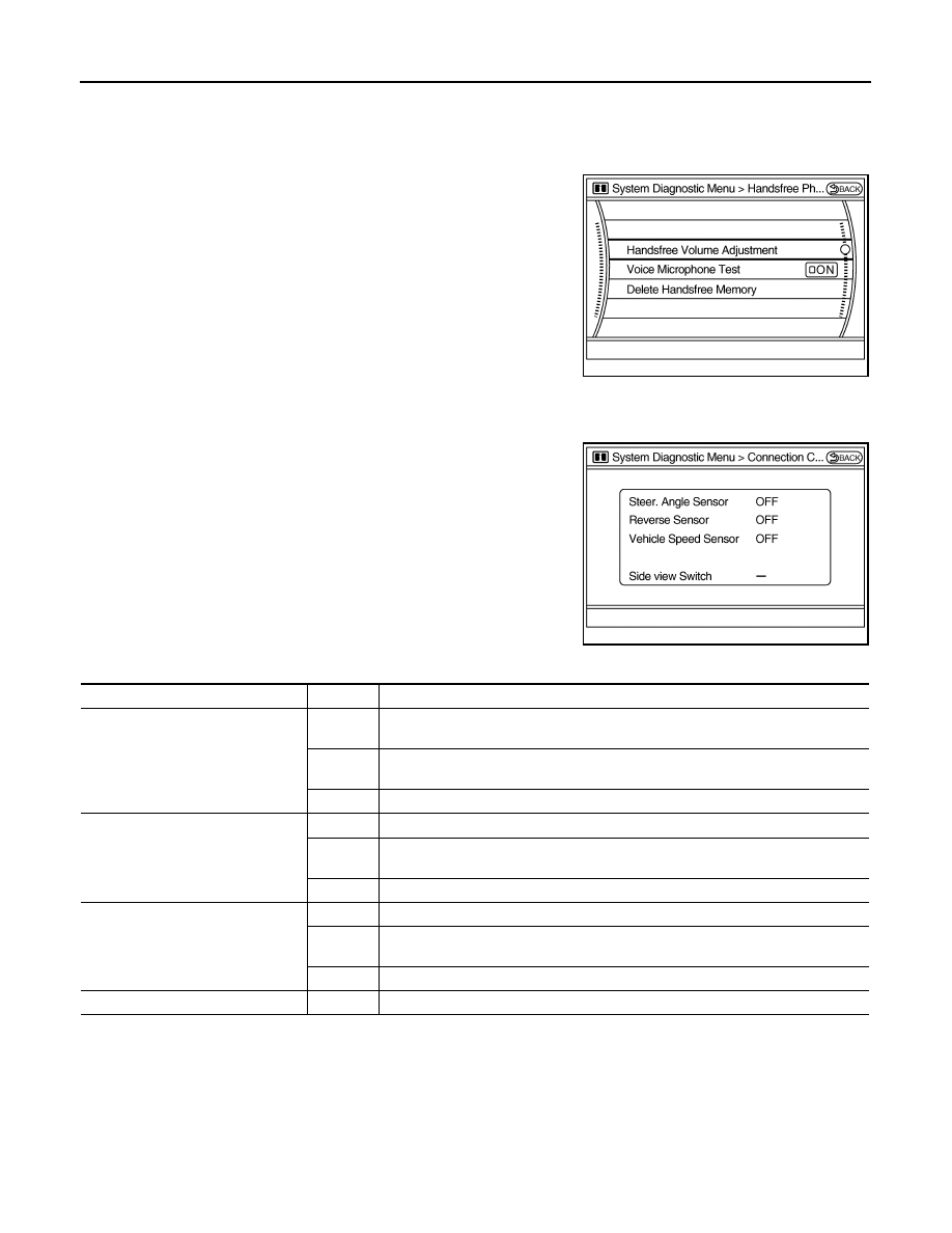
AV COMM Diagnosis
• Displays the communication status between AV control unit (mas-
ter unit) and each unit.
• The error counter displays “OK” if any malfunction was not
detected in the past and displays “0” if a malfunction is detected. It
increases by 1 if the condition is normal at the next ignition switch
ON cycle. The upper limit of the counter is 39.
• The error counter is erased if reset.
NOTE:
• AV COMM CIRCUIT
• Internal Communication Error
• Switches Connection Error
• Rearview Camera Connection Error
• iPod Connection Error
Malfunction is detected in the AV communi-
cation circuits.
Check and repair the short circuit in AV
communication circuits.
• AV COMM CIRCUIT
• Internal Communication Error
• Switches Connection Error
• iPod Connection Error
• AVM Connection Error
Malfunction is detected in the AV communi-
cation circuits.
Check and repair the short circuit in AV
communication circuits.
Error item
Detection logic
Possible malfunction factor/Action to take
Items
Display (Current)
Malfunction counter
(Past)
Tx(HVAC)
OK / UNKWN
OK / 0 – 39
Rx(ECM)
OK / UNKWN
OK / 0 – 39
Rx(Cluster)
OK / UNKWN
OK / 0 – 39
Rx(BCM)
OK / UNKWN
OK / 0 – 39
Rx(HVAC)
OK / UNKWN
OK / 0 – 39
Rx(USM)
OK / UNKWN
OK / 0 – 39
JSNIA0080GB
Items
Status
(Current)
Counter
(Past)
C Tx(ITM–PrimarySW)
OK / UNKWN
OK / 0 – 39
C Rx(PrimarySW–ITM)
OK / UNKWN
OK / 0 – 39
C Rx(STRG SW–ITM)
OK / UNKWN
OK / 0 – 39
C Rx(Audio–ITM)
OK / UNKWN
OK / 0 – 39
C Rx(Amp–ITM)
OK / UNKWN
OK / 0 – 39
C Rx(RearCamera–ITM)
OK / UNKWN
OK / 0 – 39
C Rx(XM–ITM)
OK / UNKWN
OK / 0 – 39
C Rx(iPod–ITM)
OK / UNKWN
OK / 0 – 39
C RX(AVM–ITM)
OK / UNKWN
OK / 0 – 39
C Rx(Amp–Audio)
—
—
C Rx(iPod–Audio)
OK / UNKWN
OK / 0 – 39
C Rx(Sonar–AVM)
OK / UNKWN
OK / 0 – 39
C Tx(Audio–ITM)
OK / UNKWN
OK / 0 – 39
JSNIA0081GB
AV-496
< FUNCTION DIAGNOSIS >
[BOSE AUDIO WITH NAVIGATION]
DIAGNOSIS SYSTEM (AV CONTROL UNIT)
• Any units with “—” displayed have no history of vehicle connection.
• “Audio” and “Amp” indicate the same status because “Amp” indicates the status of the amplifier integrated in AV control unit.
• “STRG SW”, “Amp” and “XM” indicate the same status as “Audio”.
Hands-Free Phone
The hands-free phone reception volume adjustment, microphone
and speaker test, and memory erase functions are also available.
Camera Cont. (With Rear View Monitor)
The two functions of “Connection Confirmation” and “Adjust Offset of Rear View Camera” are available.
CONNECTION CONFIRMATION
Steering angle sensor, reverse signal and vehicle speed sensor can
be inspected.
ADJUST OFFSET OF REAR VIEW CAMERA
JSNIA0083GB
JSNIA0084GB
Diagnosis item
Display
Vehicle status
Steer. Angle Sensor
ON
When steering the vehicle with ignition switch ON (remains ON until connection
mode is stopped when it is turned ON)
OFF
• Ignition switch at ACC
• No steering with ignition switch ON
—
Malfunction detected in camera connection recognition signal
Reverse Sensor
ON
Selector lever is in “R” with ignition switch ON.
OFF
• Ignition switch at ACC
• Selector lever is in position other than “R” with ignition switch ON
—
Malfunction detected in camera-connection recognition signal
Vehicle Speed Sensor
ON
Vehicle speed is more than 0 km/h (0 MPH) with ignition switch ON
OFF
• Ignition switch at ACC
• Vehicle speed is 0 km/h (0 MPH) with ignition switch ON
—
Malfunction detected in camera connection recognition signal
Side view Switch
—
Not used
Нет комментариевНе стесняйтесь поделиться с нами вашим ценным мнением.
Текст