Infiniti EX35. Manual — part 179
AV
DIAGNOSIS SYSTEM (AV CONTROL UNIT)
AV-497
< FUNCTION DIAGNOSIS >
[BOSE AUDIO WITH NAVIGATION]
C
D
E
F
G
H
I
J
K
L
M
B
A
O
P
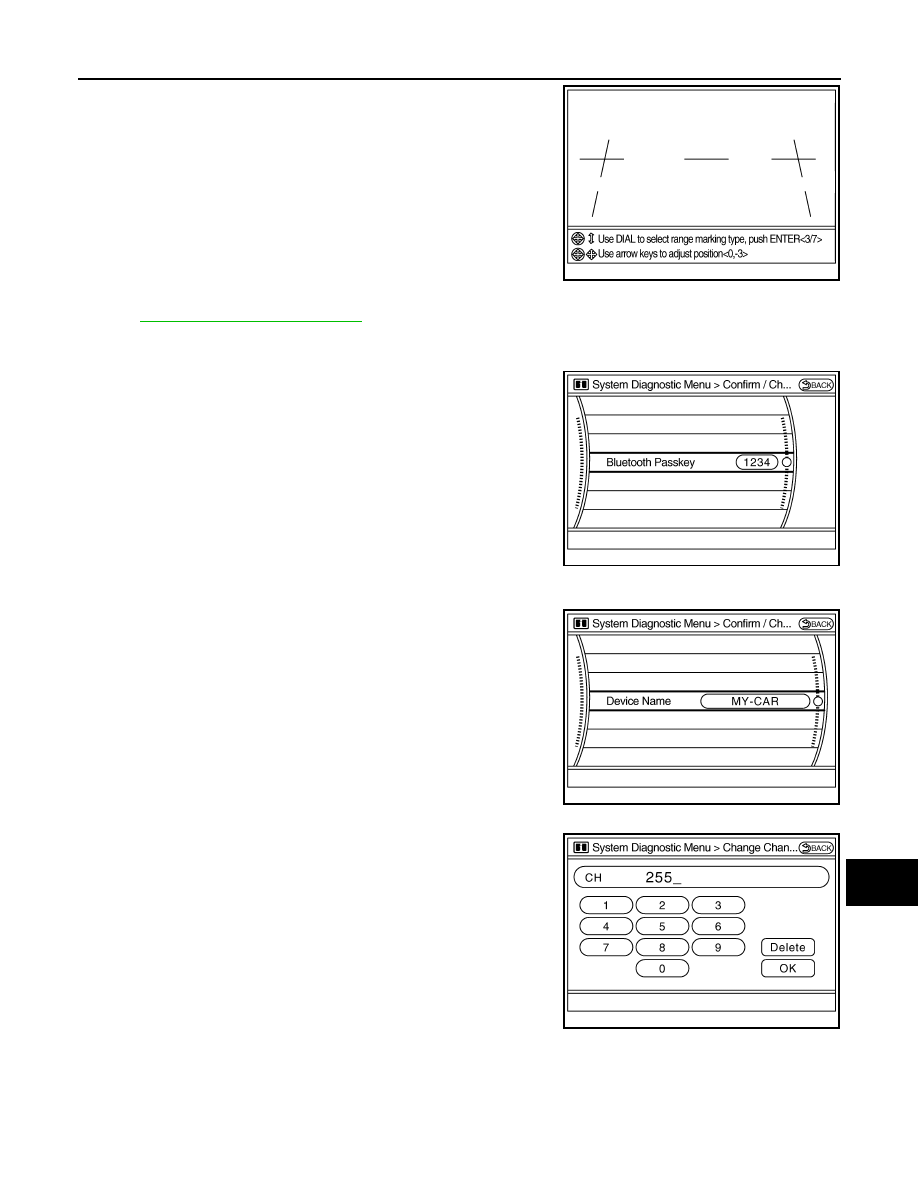
Use this mode to adjust the guide line display position of the rear
view monitor if necessary after removing the rear view monitor cam-
era.
Camera Cont. (With Around View Monitor)
AV-503, "Diagnosis Description"
.
Bluetooth
Confirm / Change Passkey
• The passkey of Bluetooth can be confirmed and changed.
• The passkey can be changed by four digits within 0 to 9.
Confirm / Change Device Name
• The device name of Bluetooth can be confirmed and changed.
• The device name can be changed by sixteen digits within A to Z
(small character can be used) and - (hyphen).
SAT
• Change Channel
- Any necessary channels required to receive traffic information from
the satellite radio system can be set.
JSNIA0085GB
JSNIA0086GB
JSNIA0087GB
JSNIA0092GB
AV-498
< FUNCTION DIAGNOSIS >
[BOSE AUDIO WITH NAVIGATION]
DIAGNOSIS SYSTEM (AV CONTROL UNIT)
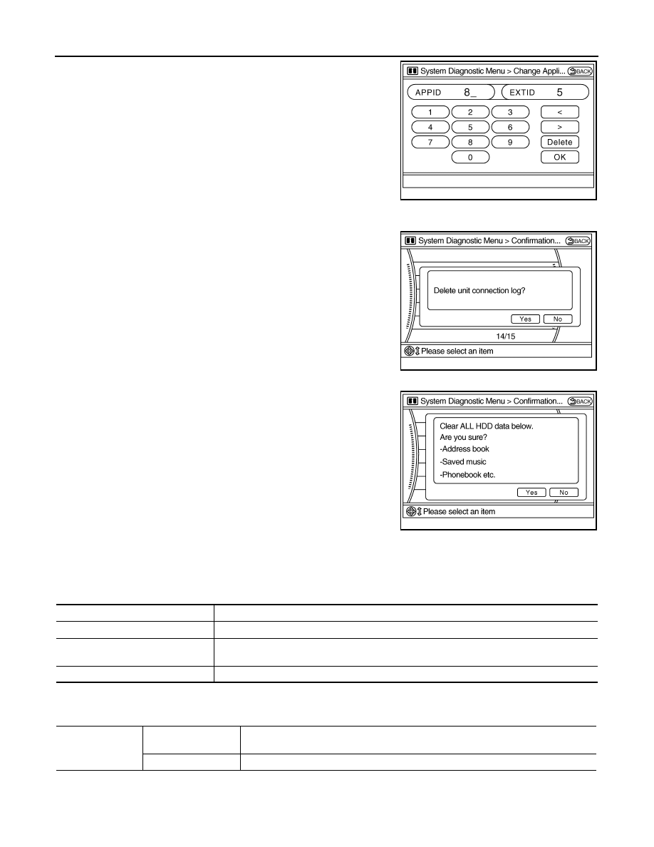
• Change Application ID
- Any application IDs required to receive traffic information from the
satellite radio system can be set.
Delete Unit Connection Log
Deletes any unit connection records and error records from AV con-
trol unit memory. (Clear the records of the unit that has been
removed.)
Initialize Settings
Deletes data stored in HDD.
CONSULT-III Function (MULTI AV)
INFOID:0000000003465022
CONSULT-III FUNCTIONS
CONSULT-III performs the following functions via the communication with AV control unit.
AV COMMUNICATION
When “AV communication” of “CAN Diag Support Monitor” is selected, the following function will be performed.
ECU IDENTIFICATION
The part number of AV control unit is displayed.
JSNIA0093GB
JSNIA0088GB
JSNIA0095GB
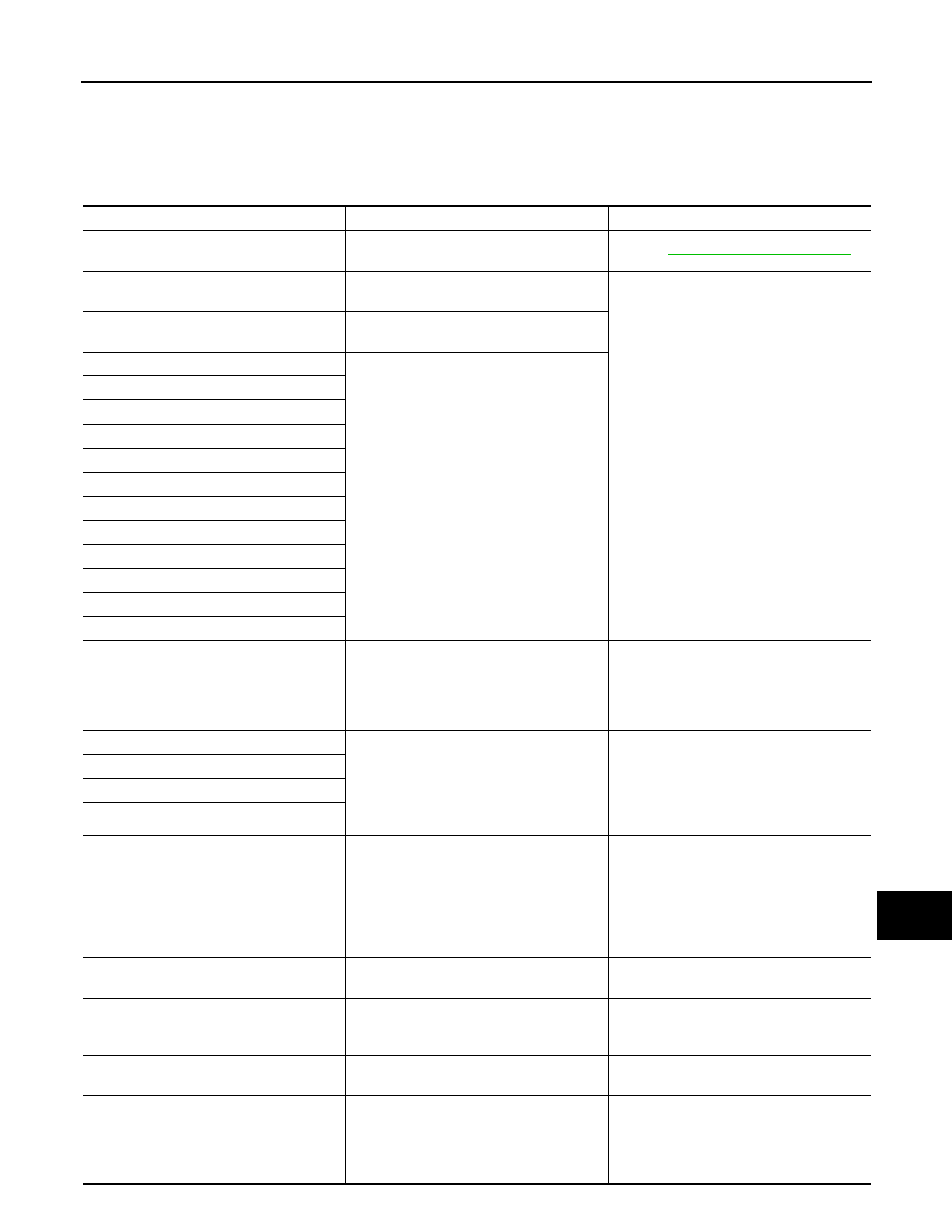
Diagnosis mode
Description
Ecu Identification
The part number of AV control unit can be checked.
Self Diagnostic Result
Performs a diagnosis on AV control unit, a connection diagnosis for the communication circuit
of the Multi AV system, and displays the current and past malfunctions collectively.
Data Monitor
The diagnosis of vehicle signal that is input to AV control unit can be performed.
AV communication
AV&NAVI C/U
Displays the communication status from AV control unit to each unit as well as the error
counter.
AUDIO
Displays AV control unit communication status and the error counter.
AV
DIAGNOSIS SYSTEM (AV CONTROL UNIT)
AV-499
< FUNCTION DIAGNOSIS >
[BOSE AUDIO WITH NAVIGATION]
C
D
E
F
G
H
I
J
K
L
M
B
A
O
P
SELF DIAGNOSIS RESULT
• In CONSULT-III self-diagnosis, self-diagnosis results and error history are displayed simultaneously.
• The timing is displayed as “0” if any of the error codes [U1000], [U1010], [U1300] or [U1310] are detected.
The counter increases by 1 if the condition is normal at the next ignition switch ON cycle.
Self-diagnosis results display item
Error item
Description
Possible malfunction factor/Action to take
CAN COMM CIRCUIT[U1000]
CAN communication malfunction is detect-
ed.
Refer to
.
CONTROL UNIT (CAN) [U1010]
CAN initial diagnosis malfunction is detect-
ed.
Replace AV control unit.
CONTROL UNIT (AV) [U1310]
AV communication circuit initial diagnosis
malfunction is detected.
Control Unit FLASH-ROM [U1200]
AV control unit malfunction is detected.
Gyro NO CONN [U1201]
CAN CONT [U1216]
BLUETOOTH CONN [U1217]
HDD CONN [U1218]
HDD READ [U1219]
XM SERIAL COMM [U1220]
HDD WRITE [U121A]
HDD COMM [U121B]
HDD ACCESS [U121C]
DSP CONN [U121D]
DSP COMM [U121E]
INTERNAL COMM [U121F]
When either one of the following items
are detected:
• Malfunction is detected in AV control unit
supply or ground circuit.
• AV control unit malfunction are detected.
• AV control unit power supply and ground
circuits.
• When there is no malfunction, AV control
unit is malfunctioning.
GPS COMM [U1204]
GPS malfunction is detected.
An intermittent error caused by strong radio
interference may be detected unless any
symptom (GPS reception error, etc.) oc-
curs.
Replace AV control unit if the malfunction
occurs constantly.
GPS ROM [U1205]
GPS RAM [U1206]
GPS RTC [U1207]
FRONT DISP CONN [U1243]
When either one of the following items
are detected:
• Display unit power supply or ground cir-
cuits malfunction are detected.
• Malfunction is detected in the communi-
cation circuits between AV control unit
and display unit.
• Display unit power supply and ground
circuits.
• Communication circuits between AV con-
trol unit and AV display unit.
GPS ANTENNA CONN [U1244]
GPS antenna connection malfunction is de-
tected.
GPS antenna.
CAMERA CONT CONN [U1250]
Malfunction is detected in the camera con-
nection recognition circuit between AV con-
trol unit and camera control unit.
Camera-connection recognition circuit be-
tween AV control unit and camera control
unit.
XM ANTENNA CONN [U1258]
Poor connection is detected in satellite ra-
dio antenna.
• Satellite radio antenna feeder.
• Satellite radio antenna.
• AV COMM CIRCUIT [U1300]
• INTERNAL COMM [U121F]
When either one of the following items
are detected:
• AV control unit power supply or ground
circuits malfunction are detected.
• AV control unit malfunction are detected.
• AV control unit power supply and ground
circuits.
• When there is no malfunction, AV control
unit is malfunctioning.

AV-500
< FUNCTION DIAGNOSIS >
[BOSE AUDIO WITH NAVIGATION]
DIAGNOSIS SYSTEM (AV CONTROL UNIT)
• AV COMM CIRCUIT [U1300]
• SWITCH CONN [U1240]
WITHOUT REAR VIEW MONITOR AND
AROUND VIEW MONITOR
When either one of the following items
are detected:
• Multifunction switch power supply or
ground circuits malfunction are detected.
• Malfunction is detected in the AV com-
munication circuits between multifunc-
tion switch and the junction between AV
control unit and iPod adapter.
• Multifunction switch power supply and
ground circuits.
• AV communication circuits between mul-
tifunction switch and the junction be-
tween AV control unit and iPod adapter.
WITH REAR VIEW MONITOR
When either one of the following items
are detected:
• Multifunction switch power supply or
ground circuits malfunction are detected.
• Malfunction is detected in the AV com-
munication circuits between multifunc-
tion switch and the junction between AV
control unit and camera control unit.
• Multifunction switch power supply and
ground circuits.
• AV communication circuits between mul-
tifunction switch and the junction be-
tween AV control unit and camera control
unit.
WITH AROUND VIEW MONITOR
When either one of the following items
are detected:
• Multifunction switch power supply or
ground circuits malfunction are detected.
• Malfunction is detected in the AV com-
munication circuits between multifunc-
tion switch and the junction between AV
control unit and around view monitor
control unit.
• Multifunction switch power supply and
ground circuits.
• AV communication circuits between mul-
tifunction switch and the junction be-
tween AV control unit and around view
monitor control unit.
• AV COMM CIRCUIT [U1300]
• REAR CAMERA LAN CONN [U1252]
Camera control unit power supply or
ground circuits malfunction is detected.
Camera control unit power supply and
ground circuits.
• AV COMM CIRCUIT [U1300]
• IPod CONN [U1254]
WITHOUT REAR VIEW MONITOR AND
AROUND VIEW MONITOR
When either one of the following items
are detected:
• iPod adapter power supply or ground cir-
cuits malfunction are detected.
• Malfunction is detected in the AV com-
munication circuits between iPod adapt-
er and the junction between AV control
unit and multifunction switch.
• iPod adapter power supply and ground
circuits.
• AV communication circuits between iPod
adapter and the junction between AV
control unit and multifunction switch.
WITH REAR VIEW MONITOR
When either one of the following items
are detected:
• iPod adapter power supply or ground cir-
cuits malfunction are detected.
• Malfunction is detected in the AV com-
munication circuits between camera con-
trol unit and iPod adapter.
• iPod adapter power supply and ground
circuits.
• AV communication circuits between cam-
era control unit and iPod adapter.
WITH AROUND VIEW MONITOR
When either one of the following items
are detected:
• iPod adapter power supply or ground cir-
cuits malfunction is detected.
• Malfunction is detected in the AV com-
munication circuits between around view
monitor control unit and iPod adapter.
• iPod adapter power supply and ground
circuits.
• AV communication circuits between
around view monitor control unit and
iPod adapter.
• AV COMM CIRCUIT [U1300]
• AROUND CAMERA CONN [U125B]
Around view monitor control unit power
supply or ground circuits malfunction is de-
tected.
Around view monitor control unit power
supply and ground circuits.
Error item
Description
Possible malfunction factor/Action to take
Нет комментариевНе стесняйтесь поделиться с нами вашим ценным мнением.
Текст