Infiniti EX35. Manual — part 99

AV
MULTI AV SYSTEM
AV-177
< FUNCTION DIAGNOSIS >
[BOSE AUDIO WITHOUT NAVIGATION]
C
D
E
F
G
H
I
J
K
L
M
B
A
O
P
• AV control unit functions by transmitting/receiving data one by one with each unit (slave unit) that configures
them completely as a master unit by connecting between units that configure the MULTI AV system with two
AV communication lines (H, L).
• Two AV communication lines (H, L) adopt a twisted pair line that is resistant to noise.
• AV control unit is connected by CAN communication, and it receives data signals from the ECM, unified
meter and A/C amp. It computes and displays fuel economy information values with the obtained informa-
tion. The transmitting/receiving of data signals is performed by BCM. In addition, it transmits the required
signal of vehicle setting and receives the response signal.
• AV control unit is connected with display and serial communication, and it transmits the required signal of
display and display control and receives the response signal from front display. Also, it is connected with sat-
ellite radio by serial communication, and it transmits the operating signal and receives the display signal.
NOTE:
AV control unit can perform CONSULT-III self-operating function and on board self-diagnosis.
• CONSULT-III self-diagnosis: refer to
AV-201, "CONSULT-III Function (MULTI AV)"
.
• On board self-diagnosis: refer to
AV-192, "Diagnosis Description"
On board self-diagnosis of TEL adapter unit can be performed.
• Refer to
AV-205, "Diagnosis Description"
for on board self-diagnosis.
AUXILIARY INPUT SYSTEM
• Image and sound can be output from an external device by connecting a device with auxiliary input jacks.
• Operation can be performed with multifunction switch and steering switch. Multifunction switch transmits
operation signal to AV control unit with communication.
HANDS-FREE PHONE SYSTEM
AUXILIARY INPUT SYSTEM
Refer to “AUXILIARY INPUT SYSTEM” shown below.
System name
System explanation
JSNIA0172GB
AV-178
< FUNCTION DIAGNOSIS >
[BOSE AUDIO WITHOUT NAVIGATION]
MULTI AV SYSTEM
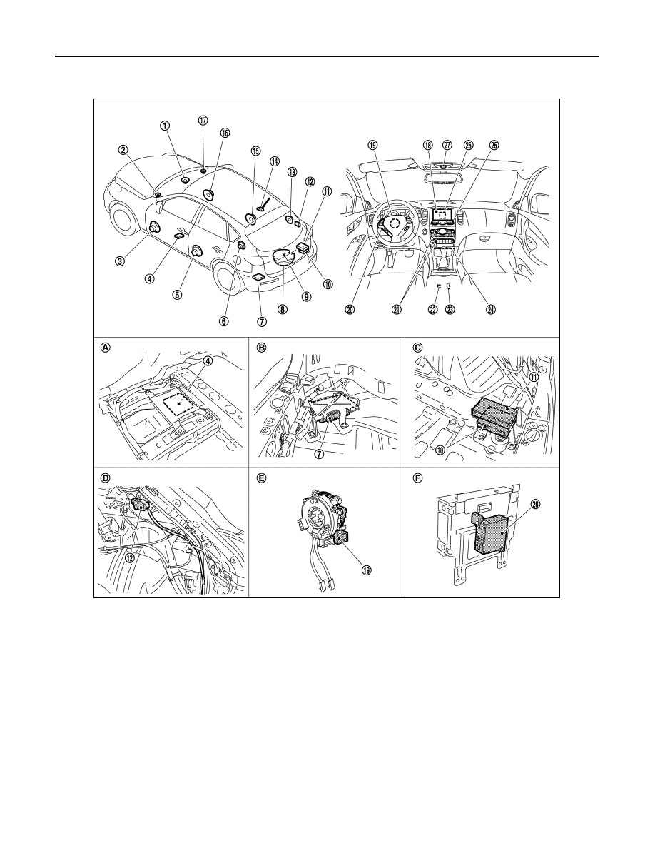
Component Parts Location
INFOID:0000000003567028
1.
Center speaker
2.
Front squawker LH
3.
Front door speaker LH
4.
Camera control unit
5.
Rear door speaker LH
6.
Rear squawker LH
7.
BOSE amp.
8.
Woofer
9.
Rear view camera
10. Satellite radio tuner
11. TEL adapter unit
12. TEL antenna
13. Rear squawker RH
14. Antenna base (antenna amp and sat-
ellite antenna)
15. Rear door speaker RH
16. Front door speaker RH
17. Front squawker RH
18. Display unit
19. Steering angle sensor
20. Steering switch
21. Preset switch
22. iPod connector
23. Auxiliary input jacks
24. AV control unit
25. Multifunction switch
26. iPod adapter
27. Microphone
A.
Under front seat (LH side)
B.
Luggage floor (LH side)
C.
Luggage floor (RH side)
D.
Luggage side RH
E.
Spiral cable part
F.
Rear view of the display unit
JPNIA0910ZZ

AV
MULTI AV SYSTEM
AV-179
< FUNCTION DIAGNOSIS >
[BOSE AUDIO WITHOUT NAVIGATION]
C
D
E
F
G
H
I
J
K
L
M
B
A
O
P
Component Description
INFOID:0000000003508653
Part name
Description
AV CONTROL UNIT
• It is the master unit of the MULTI AV system, and it is connected to each control
unit by communication. It operates each system according to communication
signals from AV control unit.
• AV control unit includes audio function and vehicle information function.
• It is connected to ECM and unified meter and A/C amp via CAN communica-
tion to obtain necessary information for the vehicle information function.
• It is connected to BCM via CAN communication transmitting/receiving for the
vehicle settings function.
• It inputs the illumination signals that are required for display dimming control.
• It inputs the signals for driving status recognition (vehicle speed, reverse and
parking brake).
• Auxiliary image signal is input from the auxiliary input jacks.
• Camera image signal is input from camera control unit.
• AV control unit recognizes the presence of camera system with camera con-
nection recognition signal.
DISPLAY UNIT
• Display image is controlled by the serial communication from AV control unit.
• RGB image signal is input from AV control unit (RGB, RGB area and RGB syn-
chronizing).
• Synchronizing signal (HP, VP) is output to AV control unit.
• Composite image signal is input from AV control unit.
BOSE AMP.
• Inputs power (amp. ON) and sound signal from AV control unit, and outputs
sound signal to woofer and each speaker.
• Input “Driver's Audio Stage” mode change signal from AV control unit.
• Woofer amp. ON signal is transmitted to woofer.
FRONT DOOR SPEAKER
• Outputs sound signal from BOSE amp.
• Outputs sound (mid and low range).
REAR DOOR SPEAKER
• Outputs sound signal from BOSE amp.
• Outputs sound (mid and low range).
FRONT SQUAWKER
• Outputs sound signal from BOSE amp.
• Outputs sound (high and mid range).
REAR SQUAWKER
• Outputs sound signal from BOSE amp.
• Outputs sound (high and mid range).
CENTER SPEAKER
• Outputs sound signal from BOSE amp.
• Outputs sound (high and mid range).
WOOFER
• Inputs power (amp. ON) and sound signal from BOSE amp.
• Outputs low-frequency sound.
MULTIFUNCTION SWITCH
• Operation panel is equipped with the centralized switch where audio and aux-
iliary input operations are integrated.
• Connected with preset switch via cable, and operation signal is transmitted to
AV control unit via AV communication.
PRESET SWITCH
• Operation panel is equipped with the centralized switch where audio and air
conditioner operations are integrated.
• Connected with multifunction switch via cable, and operation signal is transmit-
ted to AV control unit via AV communication.
• The disk ejection operating signal is performed by hardwire.
CAMERA CONTROL UNIT
• Camera image signal is input from rear view camera. Camera image signal is
output to AV control unit.
• Power (camera ON signal) is transmitted to rear view camera.
• Superimposes the guiding line and predicted course line to the camera image
that outputs to AV control unit.
• Inputs the sensor signal from steering angle sensor, and then controls the pre-
dicted course line.
• Camera control unit is connected via AV communication.
REAR VIEW CAMERA
• The image from rear camera is transmitted to camera control unit.
• It receives power (camera ON signal) from camera control unit and operates.

AV-180
< FUNCTION DIAGNOSIS >
[BOSE AUDIO WITHOUT NAVIGATION]
MULTI AV SYSTEM
STEERING ANGLE SENSOR
Steering signal necessary for possible route line control is transmitted to camera
control unit.
STEERING SWITCH
• Operations such as audio and hands-free phone are possible.
• Steering switch signal (operation signal) is output to AV control unit.
MICROPHONE
• Used only when hands-free phone is operated.
• Outputs Mic. signal (TEL voice signal) to TEL adapter unit.
• The power (Mic. power supply) is supplied from TEL adapter unit.
AUXILIARY INPUT JACKS
The image signal of the auxiliary input is output via AV control unit to display, and
it outputs the sound signal to AV control unit.
ANTENNA BASE
A radio antenna base integrated with radio antenna amp. and satellite radio an-
tenna is adopted.
ANTENNA AMP.
• Radio signal received by glass antenna is amplified and transmitted to AV con-
trol unit.
• Power (antenna amp. ON signal) is supplied from AV control unit.
SATELLITE RADIO ANTENNA
• Receives the satellite radio waves and outputs it to satellite radio tuner.
TEL ADAPTER UNIT
• Inputs the TEL voice signal from TEL antenna and outputs it to AV control unit.
• It is connected with AV control unit via AV communication and controlled with
AV control unit.
TEL ANTENNA
Receives the TEL voice signal and outputs it to TEL adapter unit.
SATELLITE RADIO TUNER
• Inputs the satellite radio signal from satellite radio antenna and outputs the
sound signal to AV control unit.
• It is controlled with AV control unit and serial communication (communication
signal and request signal).
iPod ADAPTER
• Inputs iPod sound signal from iPod
®
, and outputs iPod sound signal to AV con-
trol unit.
• Receiving/transmitting of iPod
®
operation signals are performed as follows:
- between AV control unit and iPod adapter: AV communication.
- between iPod
®
and iPod adapter: serial communication.
Part name
Description
Нет комментариевНе стесняйтесь поделиться с нами вашим ценным мнением.
Текст