Infiniti EX35. Manual — part 100
AV
AUDIO SYSTEM
AV-181
< FUNCTION DIAGNOSIS >
[BOSE AUDIO WITHOUT NAVIGATION]
C
D
E
F
G
H
I
J
K
L
M
B
A
O
P
AUDIO SYSTEM
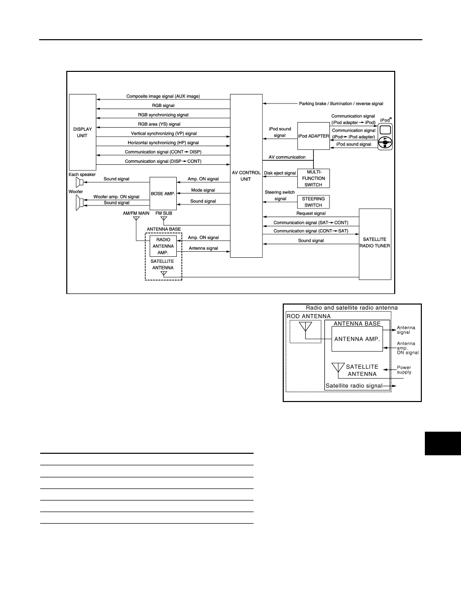
System Diagram
INFOID:0000000003508654
NOTE:
A radio antenna base integrated with radio antenna and satellite
radio antenna is adopted.
System Description
INFOID:0000000003508655
The audio system is equipped with the following functions. Each function can be operated by multifunction
switch, preset switch or steering switch. It indicates the operation status of AUDIO to display.
FUNCTION DESCRIPTION
Operating signal
Operation of the audio system can be performed with multifunction switch, preset switch or steering switch.
JSNIA0699GB
JSNIA1062GB
Function
AM/FM radio
Satellite radio
CD
iPod connection
Driver's Audio Stage
AV-182
< FUNCTION DIAGNOSIS >
[BOSE AUDIO WITHOUT NAVIGATION]
AUDIO SYSTEM
• Operating signal is transmitted to AV control unit with AV communication when it is operated by multifunction
switch or preset switch. The disk ejection operating signal is performed by hardwire.
• Operating signal is transmitted to AV control unit with steering switch signal when it is operated by steering
switch.
Screen display
• The display is switched by communication signal between display and AV control unit.
• The image signal that displays operating status is performed by the RGB signal, RGB area signal and RGB
image synchronizing signal.
AM/FM Radio Mode
• AM/FM radio tuner is built into AV control unit.
• Audio signal is received by rod antenna, next it is amplified by antenna amp., and finally it is input into AV
control unit. The FM sub antenna is installed on the back door window glass and AV control unit receives
audio signal.
• Audio signal is input to BOSE amp., BOSE amp. outputs to woofer and each speaker from AV control unit.
Satellite Radio System
• Satellite radio tuner is controlled by serial communication and request signal from AV control unit.
• Satellite radio wave is received by satellite radio antenna and is input into satellite radio tuner. Satellite radio
tuner outputs satellite radio sound signal to AV control unit. AV control unit outputs satellite radio sound sig-
nal to BOSE amp., BOSE amp. outputs the sound signal to each speaker and woofer.
CD Mode
• CD function is built into AV control unit.
• AV control unit outputs audio signals to BOSE amp., BOSE amp. outputs to woofer and each speaker when
CD is inserted to AV control unit.
iPod Connection
• Connect iPod
®
and iPod adapter with the wire harness. iPod adapter inputs iPod sound signal from iPod
®
.
When iPod mode is selected, iPod adapter outputs iPod sound signal to AV control unit. AV control unit out-
puts sound signal to BOSE amp. and BOSE amp. outputs sound signal to woofer and each speaker.
• Receiving/transmitting of iPod
®
operation signals are performed as follows:
- between AV control unit and iPod adapter: AV communication.
- between iPod
®
and iPod adapter: serial communication.
• iPod
®
connection status can be recognized whether iPod adapter receives iPod connection recognition sig-
nal.
• iPod adapter can charge iPod
®
.
Driver's Audio Stage Mode
• Driver's Audio Stage controls the speaker output characteristic by BOSE amp. so that driver seat is the cen-
ter of sound.
• ON/OFF signals of Driver's Audio Stage are transmitted from AV control unit to BOSE amp. using Mode sig-
nal.
AV
AUDIO SYSTEM
AV-183
< FUNCTION DIAGNOSIS >
[BOSE AUDIO WITHOUT NAVIGATION]
C
D
E
F
G
H
I
J
K
L
M
B
A
O
P
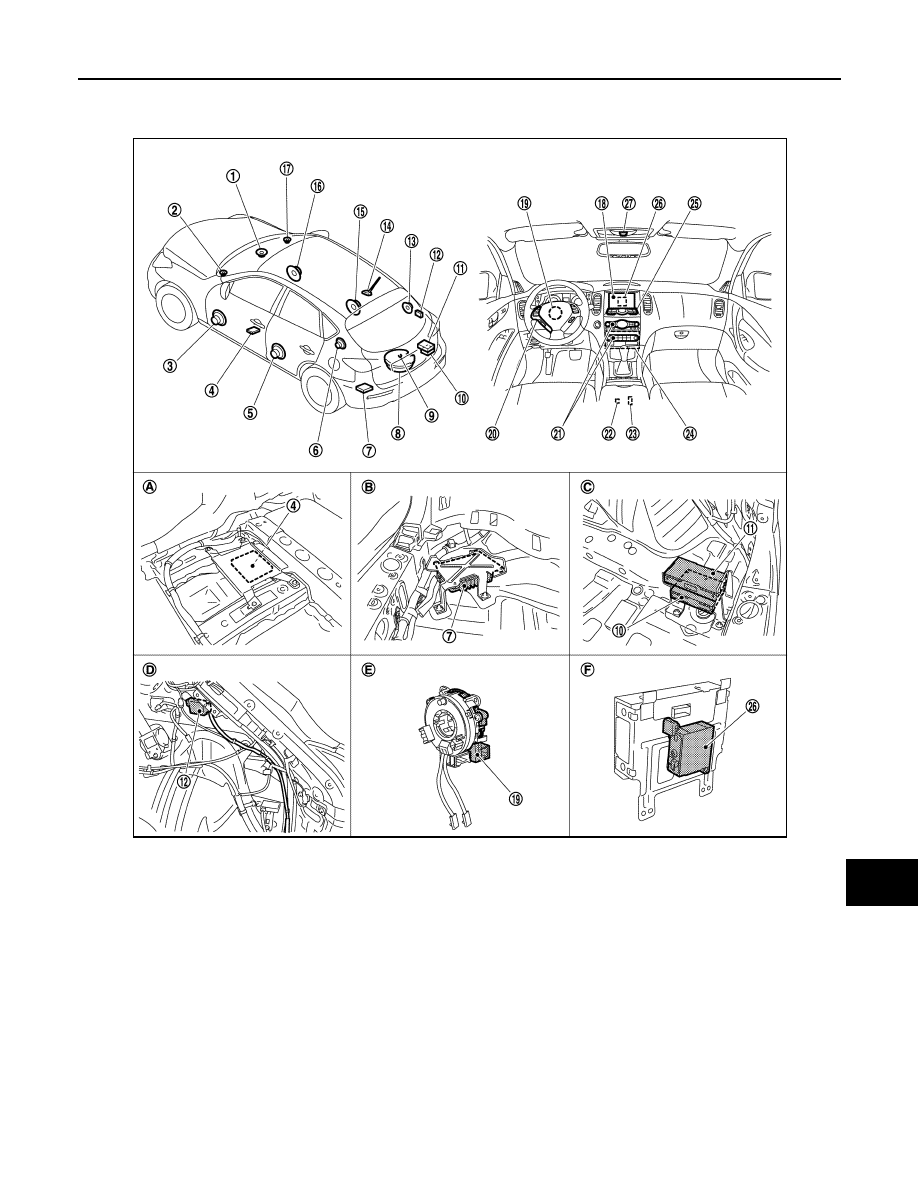
Component Parts Location
INFOID:0000000003579813
1.
Center speaker
2.
Front squawker LH
3.
Front door speaker LH
4.
Camera control unit
5.
Rear door speaker LH
6.
Rear squawker LH
7.
BOSE amp.
8.
Woofer
9.
Rear view camera
10. Satellite radio tuner
11. TEL adapter unit
12. TEL antenna
13. Rear squawker RH
14. Antenna base (antenna amp and sat-
ellite antenna)
15. Rear door speaker RH
16. Front door speaker RH
17. Front squawker RH
18. Display unit
19. Steering angle sensor
20. Steering switch
21. Preset switch
22. iPod connector
23. Auxiliary input jacks
24. AV control unit
25. Multifunction switch
26. iPod adapter
27. Microphone
A.
Under front seat (LH side)
B.
Luggage floor (LH side)
C.
Luggage floor (RH side)
D.
Luggage side RH
E.
Spiral cable part
F.
Rear view of the display unit
JPNIA0910ZZ

AV-184
< FUNCTION DIAGNOSIS >
[BOSE AUDIO WITHOUT NAVIGATION]
AUDIO SYSTEM
Component Description
INFOID:0000000003508657
Part name
Description
AV CONTROL UNIT
• The AM/FM receiving function and the CD playing function are equipped.
• BOSE amp. ON signal and sound signal are transmitted to BOSE amp.
DISPLAY UNIT
• Display image is controlled by the serial communication from AV control unit.
• RGB image signal (audio operation condition) is input from AV control unit.
BOSE AMP.
• Inputs power (amp. ON) and sound signal from AV control unit, and outputs
sound signal to woofer and each speaker.
• Input “Driver's Audio Stage” mode change signal from AV control unit.
• Woofer amp. ON signal is transmitted to woofer.
FRONT DOOR SPEAKER
• Outputs sound signal from BOSE amp.
• Outputs sound (mid and low range).
REAR DOOR SPEAKER
• Outputs sound signal from BOSE amp.
• Outputs sound (mid and low range).
FRONT SQUAWKER
• Outputs sound signal from BOSE amp.
• Outputs sound (high and mid range).
REAR SQUAWKER
• Outputs sound signal from BOSE amp.
• Outputs sound (high and mid range).
CENTER SPEAKER
• Outputs sound signal from BOSE amp.
• Outputs sound (high and mid range).
WOOFER
• Inputs power (amp. ON) and sound signal from BOSE amp.
• Outputs low-frequency sound.
MULTIFUNCTION SWITCH
• Each audio operation can be operated.
• Connected with preset switch via cable, and operation signal is transmitted to
AV control unit via AV communication.
PRESET SWITCH
• Each audio operation can be operated.
• It is connected to multifunction switch by AV communication. The operation
signal is transmitted to AV control unit.
• The CD ejection operating signal is performed by hardwire.
STEERING SWITCH
• Each audio operation can be operated.
• Steering switch signal (operation signal) is output to AV control unit.
ANTENNA BASE
A radio antenna base integrated with radio antenna amp. and satellite radio an-
tenna is adopted.
ANTENNA AMP.
• Radio signal received by glass antenna is amplified and transmitted to AV con-
trol unit.
• Power (antenna amp. ON signal) is supplied from AV control unit.
SATELLITE RADIO ANTENNA
• Receives the satellite radio waves and outputs it to satellite radio tuner.
iPod ADAPTER
• Inputs iPod sound signal from iPod
®
, and outputs iPod sound signal to AV con-
trol unit.
• Receiving/transmitting of iPod
®
operation signals are performed as follows:
- between AV control unit and iPod adapter: AV communication.
- between iPod
®
and iPod adapter: serial communication.
Нет комментариевНе стесняйтесь поделиться с нами вашим ценным мнением.
Текст