Infiniti EX35. Manual — part 1464
TM-244
< DISASSEMBLY AND ASSEMBLY >
[5AT: RE5R05A]
TRANSMISSION ASSEMBLY
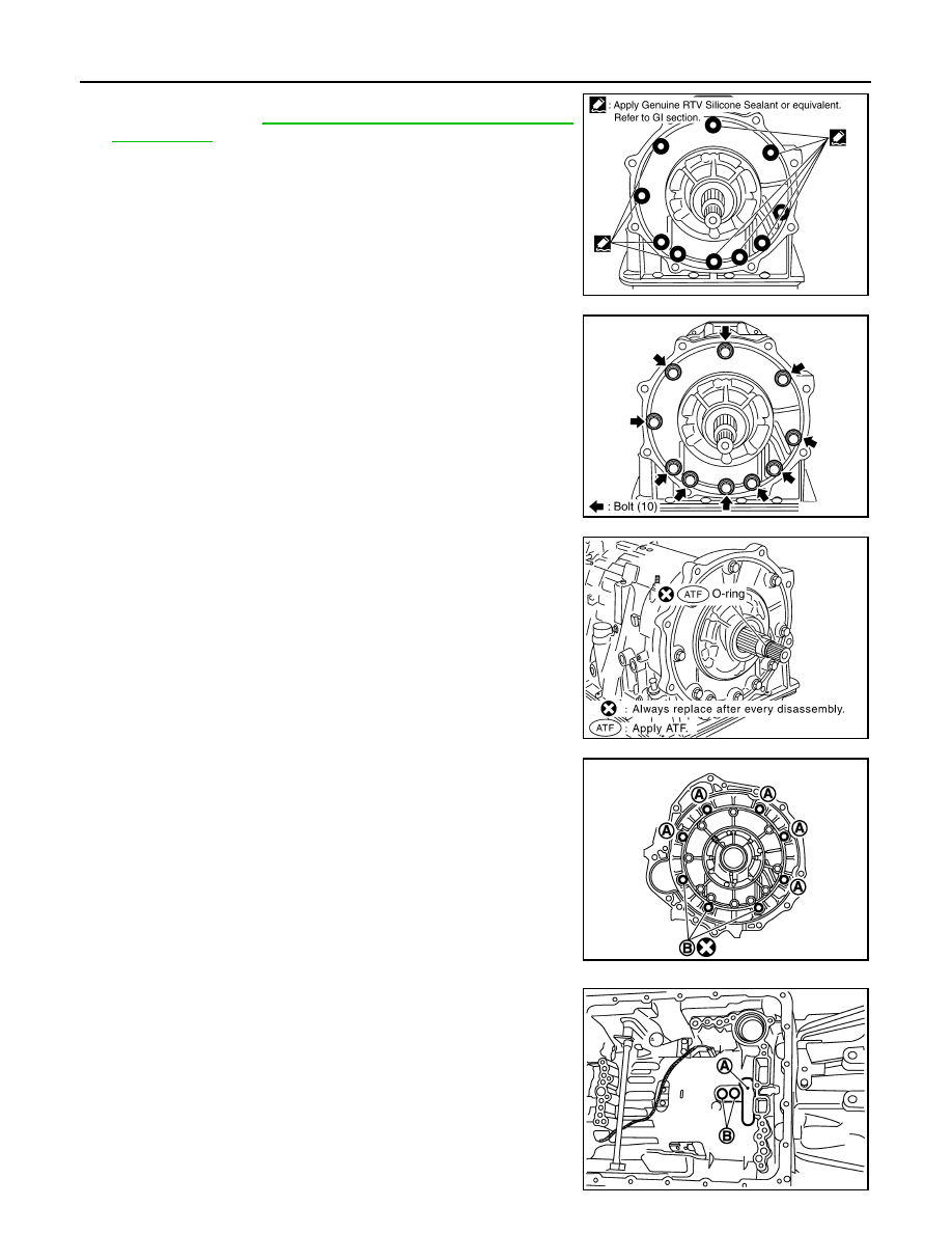
54. Apply recommended sealant (Genuine RTV Silicone Sealant or
equivalent. Refer to
GI-15, "Recommended Chemical Products
.) to oil pump assembly as shown in the figure.
CAUTION:
Completely remove all moisture, oil and old sealant, etc.
from the oil pump mounting bolts and oil pump mounting
bolt mounting surfaces.
55. Tighten oil pump bolts to the specified torque.
CAUTION:
Apply ATF to oil pump bushing.
56. Install O-ring to input clutch assembly.
57. Install converter housing to transmission case, and then tighten
converter housing bolts (A) and self-sealing bolt (B) to the spec-
ified torque.
58. Make sure that brake band (A) does not close turbine revolution
sensor hole (B).
SCIA5321E
SCIA2300E
SCIA5011E
SCIA8085E
JPDIA0020ZZ
TRANSMISSION ASSEMBLY
TM-245
< DISASSEMBLY AND ASSEMBLY >
[5AT: RE5R05A]
C
E
F
G
H
I
J
K
L
M
A
B
TM
N
O
P
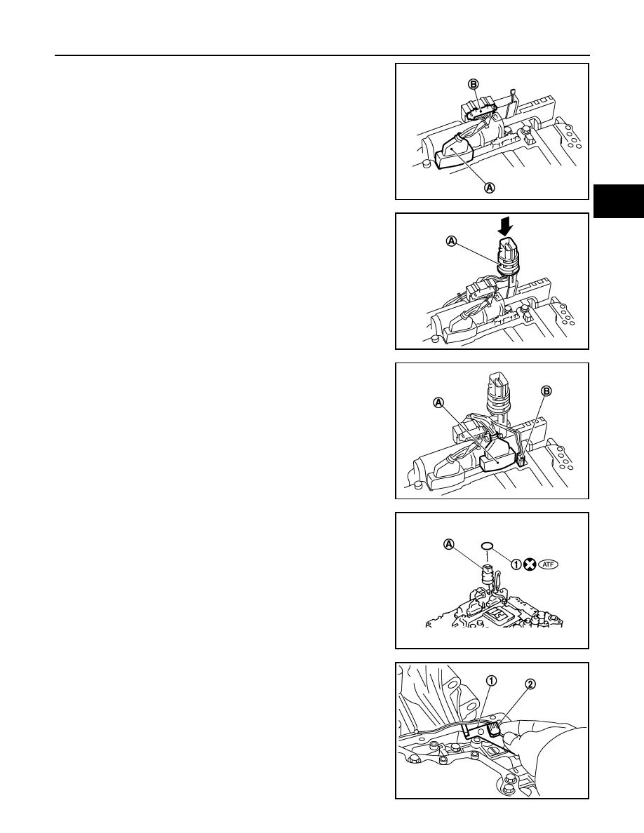
59. Connect TCM connector (A) and park/neutral position switch
connector (B).
60. Install A/T assembly harness connector (A) to control valve with
TCM.
61. Connect TCM connectors (A) and (B).
62. Install O-ring (1) to A/T assembly harness connector (A).
63. Install bracket (1) to A/T fluid temperature sensor 2 (2).
JPDIA0018ZZ
JPDIA0019ZZ
JPDIA0016ZZ
JPDIA0015ZZ
JPDIA0014ZZ
TM-246
< DISASSEMBLY AND ASSEMBLY >
[5AT: RE5R05A]
TRANSMISSION ASSEMBLY
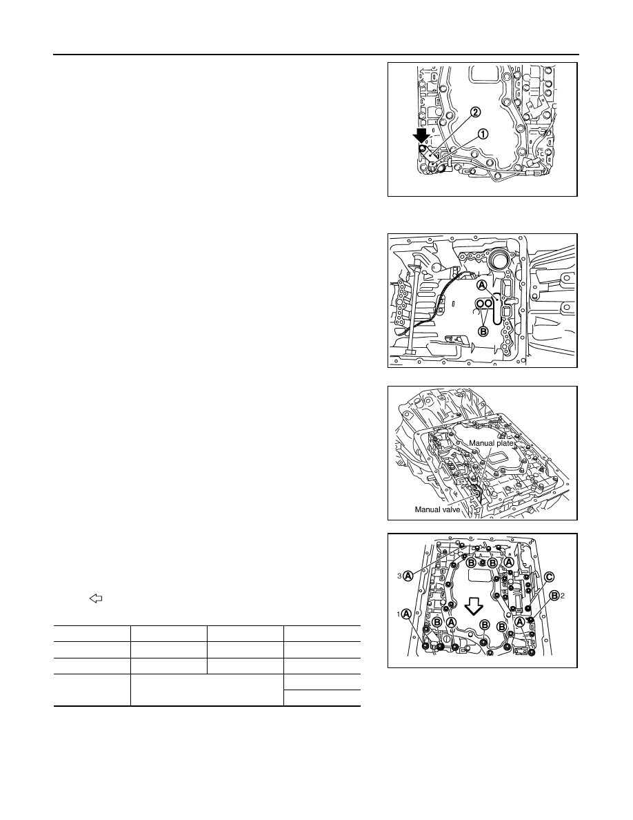
64. Install A/T fluid temperature sensor 2 (1) [with bracket (2)] in
control valve with TCM. Tighten A/T fluid temperature sensor 2
bolt to the specified torque.
CAUTION:
Adjust bolt hole of bracket to bolt hole of control valve.
65. Install control valve with TCM in transmission case.
CAUTION:
• Make sure that turbine revolution sensor securely installs
turbine revolution sensor hole (B).
• Hang down revolution sensor harness toward outside so
as not to disturb installation of control valve with TCM.
• Adjust A/T assembly harness connector of control valve
with TCM to terminal hole of transmission case.
• Assemble it so that manual valve cutout is engaged with
manual plate projection.
66. Install bolts (A), (B) and (C) in control valve with TCM. Tighten
bolt 1, 2 and 3 temporarily to prevent dislocation. After that
tighten them in order (1
→
2
→
3), and then tighten other bolts.
Tighten control valve with TCM bolts to the specified torque.
JPDIA0013ZZ
A
: Brake band
JPDIA0020ZZ
SCIA5035E
: Front
Bolt symbol
A
B
C
Number of bolts
5
6
1
Length
mm (in)
42 (1.65)
55 (2.17)
40 (1.57)
Tightening torque
N·m (km-g, in-lb)
7.9 (0.81, 70)
With ATF applied
7.9 (0.81, 70)
SCIA8078E
TRANSMISSION ASSEMBLY
TM-247
< DISASSEMBLY AND ASSEMBLY >
[5AT: RE5R05A]
C
E
F
G
H
I
J
K
L
M
A
B
TM
N
O
P
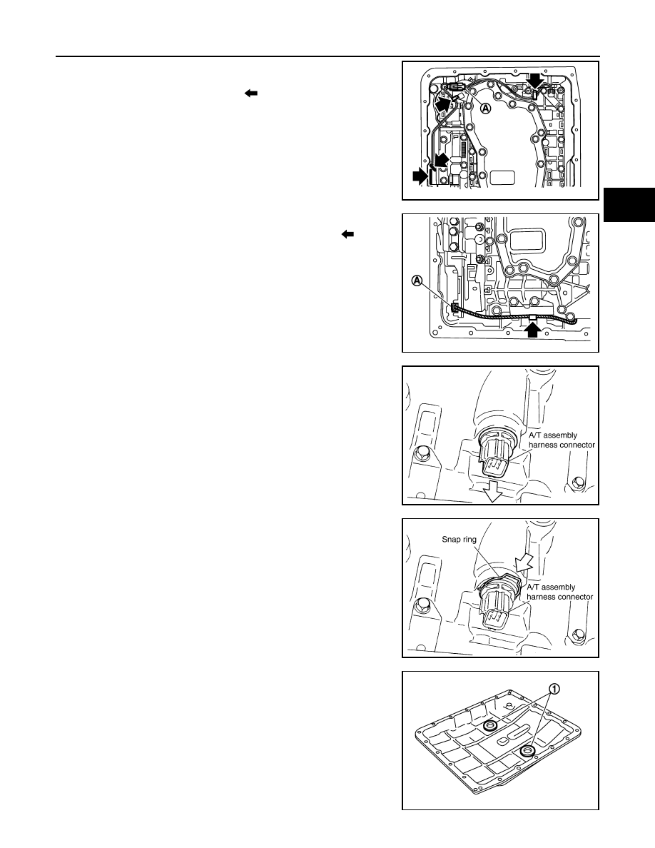
67. Connect A/T fluid temperature sensor 2 connector (A).
68. Engage terminal cord assembly and A/T fluid temperature sen-
sor 2 harness with terminal clips (
).
69. Connect revolution sensor connector (A).
70. Engage revolution sensor harness with terminal clip (
).
71. Pull down A/T assembly harness connector.
CAUTION:
Be careful not to damage connector.
72. Install snap ring to A/T assembly harness connector.
73. Install magnets (1) in oil pan.
SCIA8124E
JPDIA0011ZZ
SCIA5299E
SCIA5300E
JPDIA0009ZZ
Нет комментариевНе стесняйтесь поделиться с нами вашим ценным мнением.
Текст