Infiniti EX35. Manual — part 1399
STR-2
< BASIC INSPECTION >
DIAGNOSIS AND REPAIR WORKFLOW
BASIC INSPECTION
DIAGNOSIS AND REPAIR WORKFLOW
Work Flow
INFOID:0000000003131846
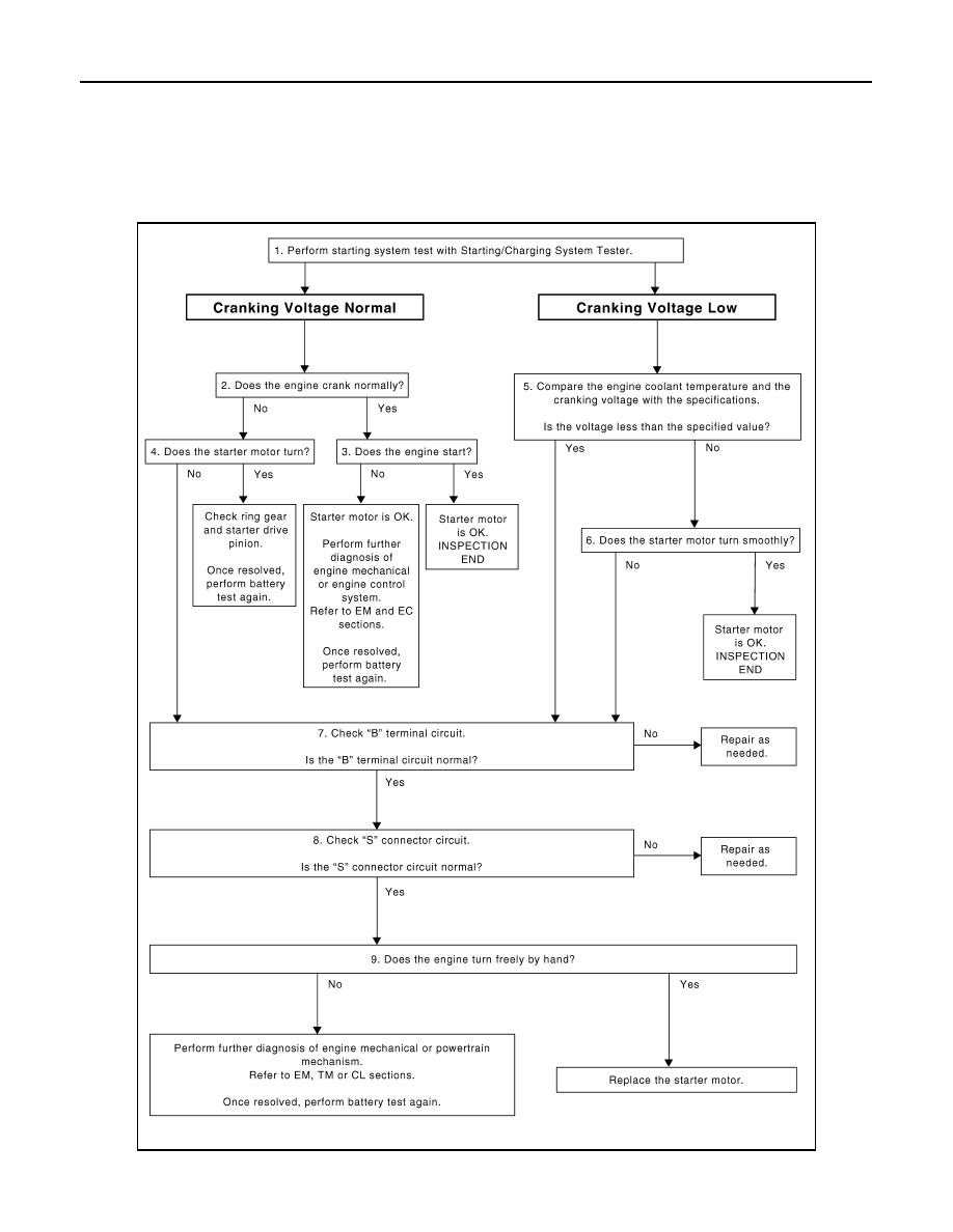
OVERALL SEQUENCE
DETAILED FLOW
JSBIA0001GB

DIAGNOSIS AND REPAIR WORKFLOW
STR-3
< BASIC INSPECTION >
C
D
E
F
G
H
I
J
K
L
M
A
STR
N
P
O
NOTE:
To ensure a complete and thorough diagnosis, the battery, starter motor and alternator test segments must be
done as a set from start to finish.
1.
DIAGNOSIS WITH STARTING/CHARGING SYSTEM TESTER
Perform the starting system test with Starting/Charging System Tester (SST: J-44373). For details and operat-
ing instructions, refer to Technical Service Bulletin.
Test result
CRANKING VOLTAGE NORMAL>>GO TO 2.
CRANKING VOLTAGE LOW>>GO TO 5.
CHARGE BATTERY>>Perform the slow battery charging procedure. (Initial rate of charge is 10A for 12
hours.) Perform battery test again. Refer to Technical Service Bulletin.
REPLACE BATTERY>>Before replacing battery, clean the battery cable clamps and battery posts. Perform
battery test again. Refer to Technical Service Bulletin. If second test result is “REPLACE BAT-
TERY”, then do so. Perform battery test again to confirm repair.
2.
CRANKING CHECK
Check that the starter motor operates correctly.
Does the engine crank normally?
YES
>> GO TO 3.
NO
>> GO TO 4.
3.
ENGINE START CHECK
Check that the engine starts.
Does the engine start?
YES
>> Starter motor is OK. INSPECTION END
NO
>> Perform further diagnosis of engine mechanical or engine control system. Refer EM and EC sec-
tions. Once resolved, perform battery test again.
4.
STARTER MOTOR ACTIVATION
Check that the starter motor operates.
Does the starter motor turn?
YES
>> Check ring gear and starter motor drive pinion. Once resolved, perform battery test again.
NO
>> GO TO 7.
5.
COMPARISON BETWEEN ENGINE COOLANT AND CRANKING VOLTAGE
Compare the engine coolant temperature and the cranking voltage with the specifications.
Minimum Specification of Cranking Voltage Referencing Coolant Temperature
Is the voltage less than the specified value?
YES
>> GO TO 7.
NO
>> GO TO 6.
6.
STARTER OPERATION
Check the starter operation status.
Does the starter motor turn smoothly?
YES
>> Starter motor is OK. INSPECTION END
NO
>> GO TO 7.
7.
“B” TERMINAL CIRCUIT INSPECTION
Check “B” terminal circuit. Refer to
.
Is “B” terminal circuit normal?
Engine coolant temperature [
°
C (
°
F)]
Voltage [V]
−
30 to
−
20 (
−
22 to
−
4)
8.6
−
19 to
−
10 (
−
2 to 14)
9.1
−
9 to 0 (16 to 32)
9.5
More than 1 (More than 34)
9.9

STR-4
< BASIC INSPECTION >
DIAGNOSIS AND REPAIR WORKFLOW
YES
>> GO TO 8.
NO
>> Repair as needed.
8.
“S” CONNECTOR CIRCUIT INSPECTION
Check “S” connector circuit. Refer to
Is “S” connector circuit normal?
YES
>> GO TO 9.
NO
>> Repair as needed.
9.
ENGINE ROTATION STATUS
Check that the engine can be rotated by hand.
Does the engine turn freely by hand?
YES
>> Replace starter motor.
NO
>> Perform further diagnosis of engine mechanical or powertrain mechanism.Once resolved, perform
battery test again. Refer to Technical Service Bulletin.
STARTING SYSTEM
STR-5
< FUNCTION DIAGNOSIS >
C
D
E
F
G
H
I
J
K
L
M
A
STR
N
P
O
FUNCTION DIAGNOSIS
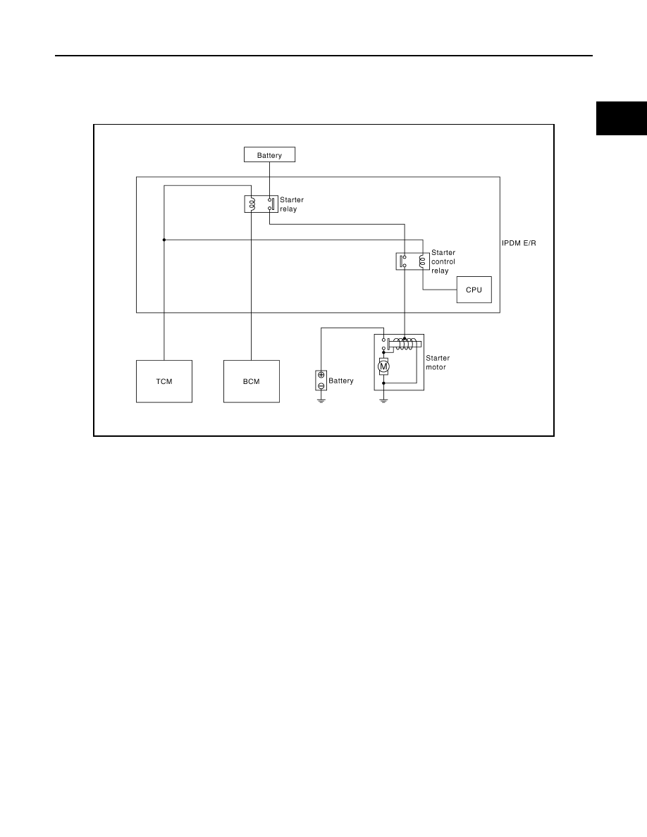
STARTING SYSTEM
System Diagram
INFOID:0000000003131847
System Description
INFOID:0000000003131848
The starter motor plunger closes and provides a closed circuit between the battery and starter motor. The
starter motor is grounded to the engine block. With power and ground supplied, cranking occurs and the
engine starts.
JPBIA0395GB
Нет комментариевНе стесняйтесь поделиться с нами вашим ценным мнением.
Текст