Infiniti EX35. Manual — part 1397

STC-14
< ECU DIAGNOSIS >
[EPS]
POWER STEERING CONTROL UNIT
CAUTION:
When using circuit tester or oscilloscope to measure voltage for inspection, be sure not to forcibly extend any connector ter-
minals.
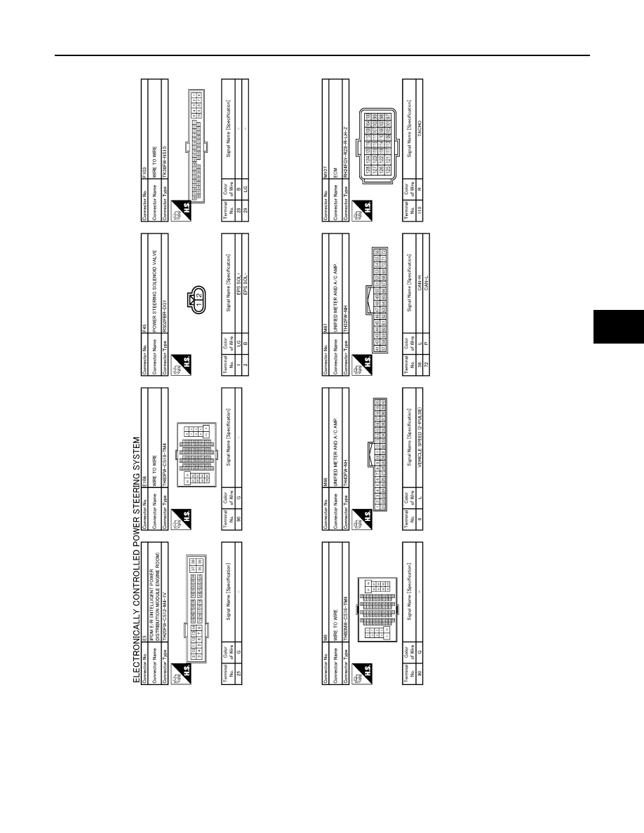
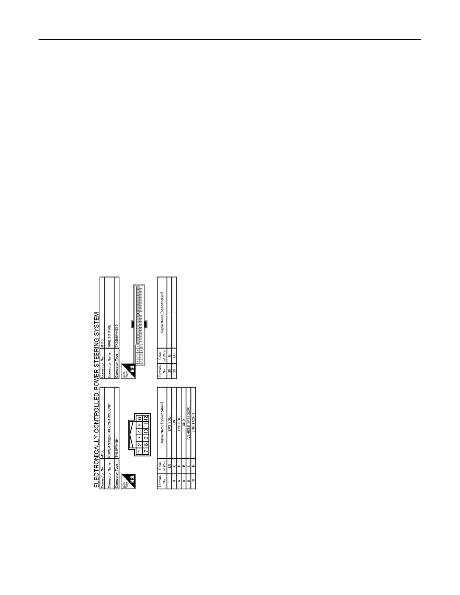
Wiring Diagram - ELECTRONICALLY CONTROLLED POWER STEERING SYSTEM -
INFOID:0000000003738699
JCGWM0077GB
POWER STEERING CONTROL UNIT
STC-15
< ECU DIAGNOSIS >
[EPS]
C
D
E
F
H
I
J
K
L
M
A
B
STC
N
O
P
JCGWM0078GB
STC-16
< ECU DIAGNOSIS >
[EPS]
POWER STEERING CONTROL UNIT
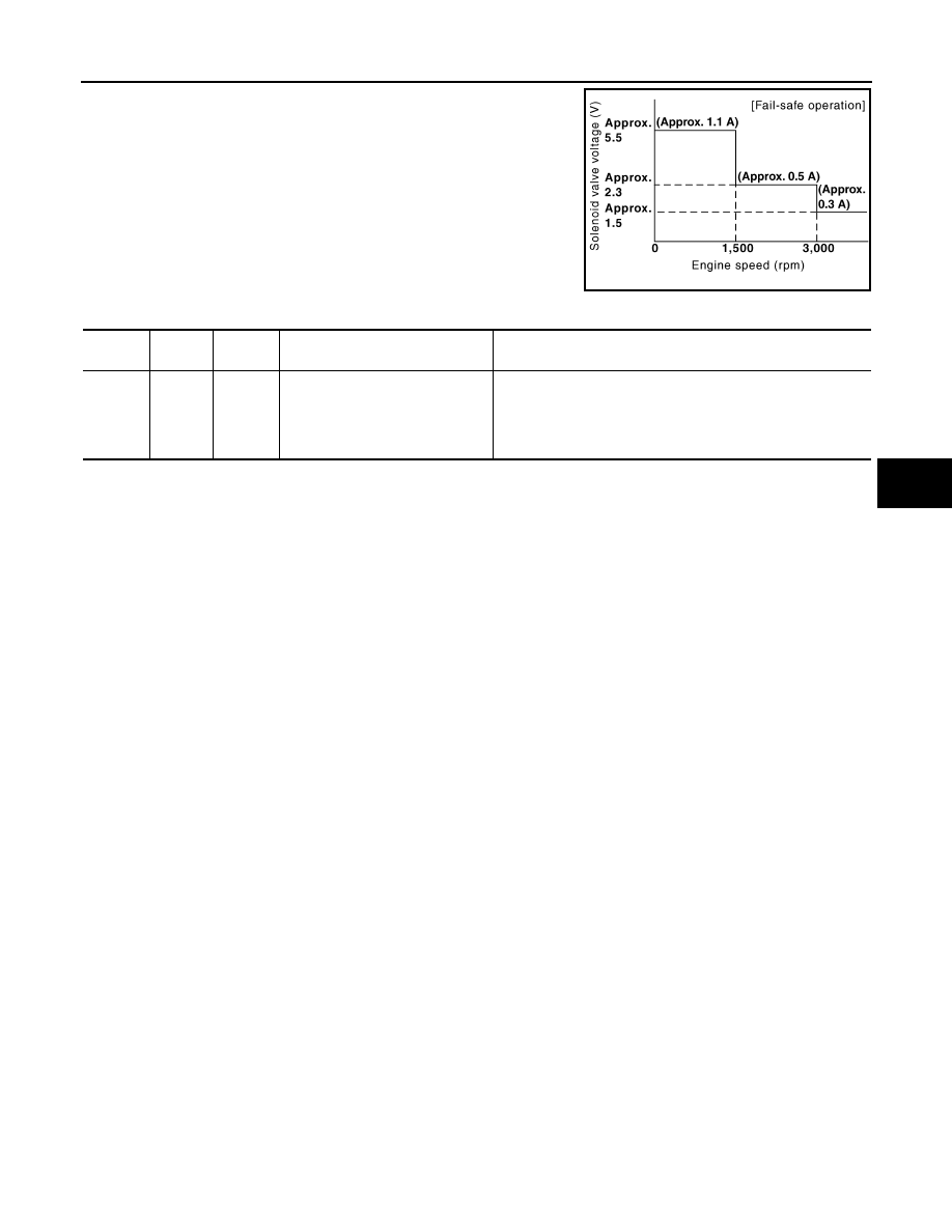
Fail-Safe
INFOID:0000000003552484
EPS system
JCGWM0079GB
POWER STEERING CONTROL UNIT
STC-17
< ECU DIAGNOSIS >
[EPS]
C
D
E
F
H
I
J
K
L
M
A
B
STC
N
O
P
• EPS system enters the fail-safe mode (that allows the steering
force to be controlled without impairing the drivability) if any of the
input/output values to/from EPS system (power steering control
unit) deviate from the standard range.
NOTE:
The system enters the fail-safe mode if the engine speed remains
at 1,500 rpm or more for over 10 seconds while the vehicle is
stopped. This is normal.
• The fail-safe function is canceled when a vehicle speed signal of 2
km/h (1.2 MPH) or more is inputted or the ignition switch is turned
OFF
→
ON. EPS system restores the normal operation at that time.
JSGIA0368GB
Mode
Warn-
ing lamp
DTC
Detection point (malfunction part)
Error area and root cause
Fail-safe
function
—
—
Vehicle speed signal input
• Engine speed is 1,500 rpm or more and there is no vehicle
speed signal input for over 10 seconds during vehicle travel.
• Vehicle speed signal has abruptly dropped from 30 km/h (19
MPH) or more to 2 km/h (1.2 MPH) or less within 1.4 sec-
onds.
Нет комментариевНе стесняйтесь поделиться с нами вашим ценным мнением.
Текст